
OTL amplifier circuit diagram

The OTL amplifier circuit operates by directly connecting the output stage to the speaker without the use of a traditional output transformer. This design is advantageous as it minimizes the weight and bulk of the amplifier while maintaining high fidelity audio output. The 100 mW power rating indicates that the circuit is suitable for low to moderate volume applications, typically found in consumer electronics like radios and small audio amplifiers.
In terms of design, the OTL amplifier utilizes transistors or vacuum tubes in its output stage, which are selected for their linear amplification characteristics. The choice of components significantly affects the overall performance, including distortion levels and frequency response. The inclusion of a capacitor in the output stage serves to block any DC offset, ensuring that only the AC audio signal reaches the speaker. This capacitor must be carefully chosen to handle the expected frequency range and power levels without introducing significant phase shift or distortion.
The frequency response of the OTL amplifier is crucial, particularly in radio applications where clarity and fidelity are paramount. The circuit is designed to have a flat frequency response across the audible range, typically from 20 Hz to 20 kHz. This is achieved through careful component selection and layout, ensuring that signal integrity is maintained throughout the circuit.
The efficiency of the OTL amplifier is another key feature, as it allows for longer operation times in battery-powered devices and reduces heat generation, which can enhance reliability. The low nonlinear distortion characteristic is particularly beneficial, as it ensures that the audio output remains true to the original signal, providing a more enjoyable listening experience.
Overall, the OTL amplifier circuit represents a sophisticated solution for applications requiring compact, efficient, and high-quality audio amplification. Its design principles and operational characteristics make it a valuable component in modern electronic devices, particularly in the realm of audio and broadcasting technologies.The following diagram shows an output power of radio 1OOmW common OTL amplifier circuit. The circuit output transformer, and a capacitor together with the speaker units. Frequency characteristics OTL amplifier circuit with good nonlinear distortion characteristics and high efficiency, widely used in televisions, amplifiers and other electronic devices. FIG OTL amplifier circuit diagram of the radio
Related Circuits

This is a simple yet effective charger for lead-acid batteries. It utilizes a 12-volt car bulb as both a current regulator and a charge status indicator. The described circuit is an innovative approach to charging lead-acid batteries. It employs...
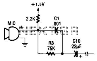
This circuit is suitable for using an electret microphone for various applications. A 1.5-V battery is utilized. CI and R3 provide treble boost and bass cut; they can be eliminated if desired. The described circuit employs an electret microphone, which...
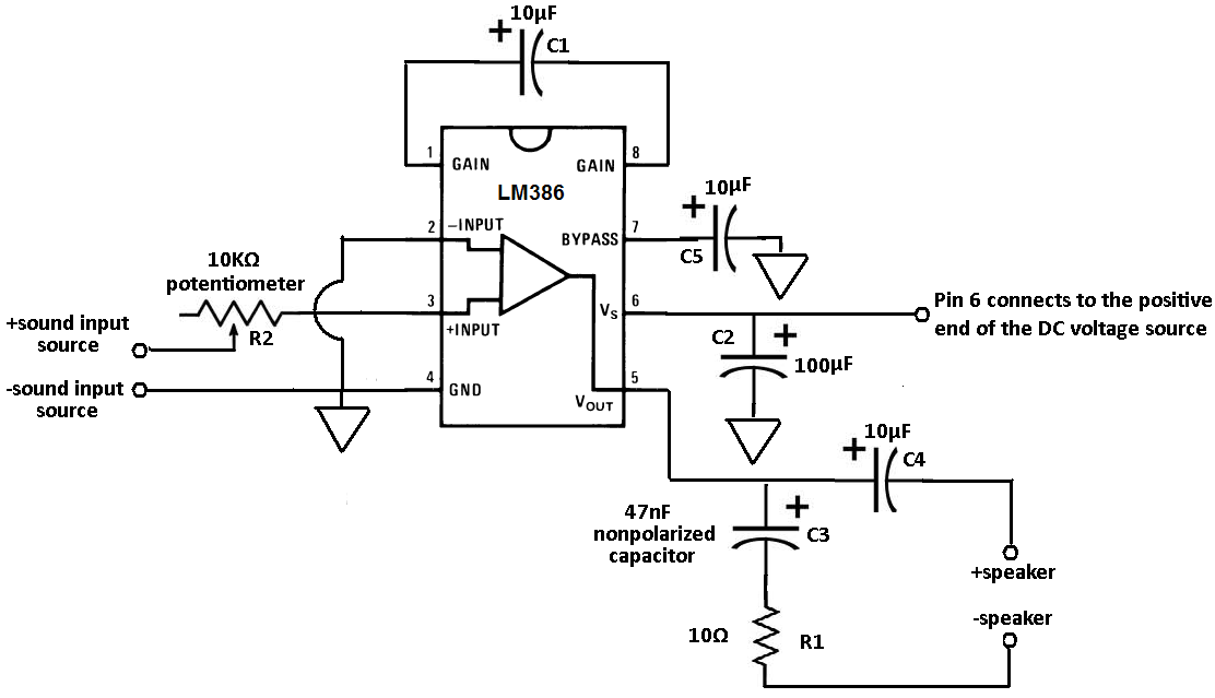
Terminals 1 and 8 serve as the gain control for the amplifier. Adjustments to the gain can be made by connecting a resistor and capacitor, or just a capacitor, between these terminals. In this circuit, a 10 µF capacitor...
A straightforward method to create a speaker transformer involves winding turns around a ferrite rod. The primary winding consists of 300 turns of 0.01mm wire, which is very fine, wound over the secondary and concluding with a loop of...
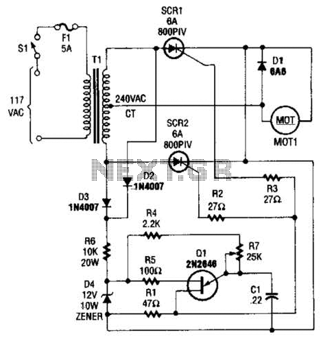
The speed-control switch provides effective control and stability across its entire operating range. This circuit utilizes two SCR devices arranged in a full-wave configuration to manage the DC power supplied to a motor. A center-tapped transformer is employed to...
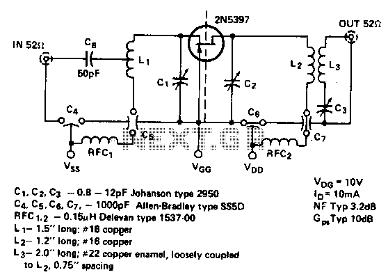
This is a low noise amplifier with a typical noise figure of 3 dB and approximately 10 dB of gain, operating within the frequency range of 450-470 MHz. It is designed for VHF two-way applications. The described low noise amplifier...