
Speed-Control Switch Circuit

The speed-control switch circuit employs a dual SCR arrangement to facilitate the control of DC power to a motor, allowing for variable speed operation. The full-wave configuration of the SCRs enables efficient power delivery by allowing both halves of the AC waveform to be utilized, thereby improving the overall efficiency of the motor control system.
The circuit begins with a center-tapped transformer that provides the necessary AC voltage. The center tap serves as a neutral point, allowing the two SCRs to be triggered alternately, thus controlling the average voltage and current supplied to the motor. This method of control is advantageous as it minimizes power losses compared to other control methods, such as resistive control.
The SCRs are triggered into conduction by a gate signal, which can be modulated to adjust the firing angle of the SCRs. By varying the firing angle, the effective voltage applied to the motor can be controlled, resulting in variable speed operation. This provides the user with the ability to finely tune the motor speed according to specific operational requirements.
In addition to the SCRs and transformer, the circuit may include additional components such as diodes for flyback protection, capacitors for filtering, and resistors for biasing and limiting current. Proper heat dissipation methods must also be considered, as SCRs can generate significant heat during operation.
Overall, this speed-control switch circuit is an effective solution for applications requiring precise control of motor speed, combining simplicity with robust performance. The speed-control switch offers reasonably good control and stability to both ends of its operating range. This circuit uses two SCR devices in a full-wave configuration to control the dc power to a motor. A center-tapped transformer is used to supply the SCRs.
Related Circuits
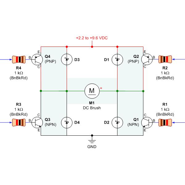
Selecting the appropriate DC motor is essential for constructing mobile robots. Testing DC motors is straightforward and can be accomplished by assembling a basic DC motor circuit. The components needed for this circuit include a DC motor, a battery...
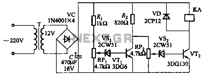
The circuit employs a transistor control mechanism. When the grid voltage is within the normal range, relay KA is activated, supplying power to the load. If the grid voltage falls below the minimum allowable threshold (adjustable via potentiometer RPz)...
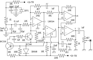
This circuit can be utilized in intercom systems, walkie-talkies, low-power transmitters, and packet radio receivers. Transistors T1 and T2 constitute the microphone preamplifier. Resistor R1 provides the necessary bias for the condenser microphone, while preset VR1 serves as a...
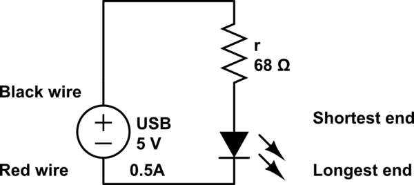
The LED operates at 3V, and based on information available online, a blue LED typically supports a maximum current of 0.03A. Given the available current from the USB source, the intention is to construct a parallel circuit. However, the...
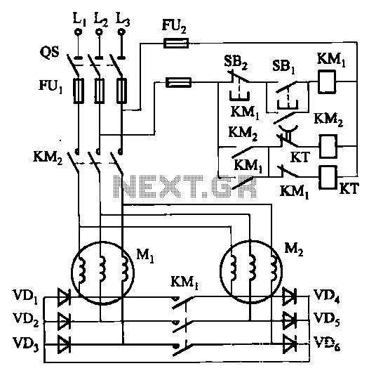
The circuit depicted in Figure 3-157 is designed for motors with a capacity of no more than 11 kW, requiring precise stopping capabilities. Upon shutdown, contact KMi releases, and the motor stator windings are configured into a three-phase rectifier...
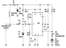
The sections available in this datasheet cover general design considerations for the 555 timer, frequently asked application questions (FAQ), design formulas, and examples of innovative applications. Examples of applications include a Missing Pulse Detector, Pulse Width Modulation (PWM), Tone...