
Tricky 12V Battery Charger Circuit

The described circuit is an innovative approach to charging lead-acid batteries. It employs a 12-volt car bulb, which serves a dual purpose. As a current regulator, the bulb limits the current flowing into the battery, preventing overcharging and potential damage. The brightness of the bulb also acts as an indicator of the charge status—the brighter the bulb, the higher the current flow, indicating that the battery is in the charging phase. As the battery reaches its full charge, the current decreases, resulting in a dimmer bulb, which signals that the charging process is nearing completion.
The circuit can be constructed using a few basic components: a transformer to step down the mains voltage to a suitable level, a rectifier to convert AC to DC, the 12-volt car bulb, and the lead-acid battery. The transformer should be rated appropriately for the desired output current and voltage. A bridge rectifier can be used to ensure the current flows in the correct direction to charge the battery.
When designing this circuit, attention must be paid to the specifications of the car bulb, as it determines the maximum current that can flow to the battery. Additionally, proper heat dissipation methods should be considered to ensure that the bulb does not overheat during operation.
This charger is particularly useful for applications where simplicity and cost-effectiveness are priorities, making it suitable for DIY enthusiasts and small-scale battery charging tasks.Here is a crude but efficient tricky charger for Lead Acid Battery. It uses a 12 volt car bulb as current regulator and charge status indicator. The bright.. 🔗 External reference
Related Circuits

A flashing LED indicates the need to water a plant in a 3V powered circuit. This circuit is designed to signal when a plant requires water. A LED flashes at a specified interval. This circuit operates on a 3V power...
A fingerprint door lock system is being considered for implementation. The primary component is a fingerprint reader that, upon recognizing a valid fingerprint, will instruct an Arduino microcontroller to activate a locking mechanism for a predetermined duration. The locking...

This LED VU Meter (volume unit) is designed to monitor and display power levels present at the speaker terminals of a stereo audio power amplifier. The levels are represented in ten discrete steps using ten LEDs for each channel,...
A relay (RL1) is activated with a 100-second delay when a +12V power supply is connected to the circuit. Figure 2 illustrates a relay timer circuit utilizing a 555 timer, featuring two time ranges: 6-60 seconds and 1-10 minutes...

A simple 16-volt switching power supply circuit can be constructed using the provided diagram, which is based on the MAX668 constant-frequency, pulse-width modulating (PWM), current-mode DC-DC controller. This integrated circuit is designed for a wide range of DC-DC conversion...
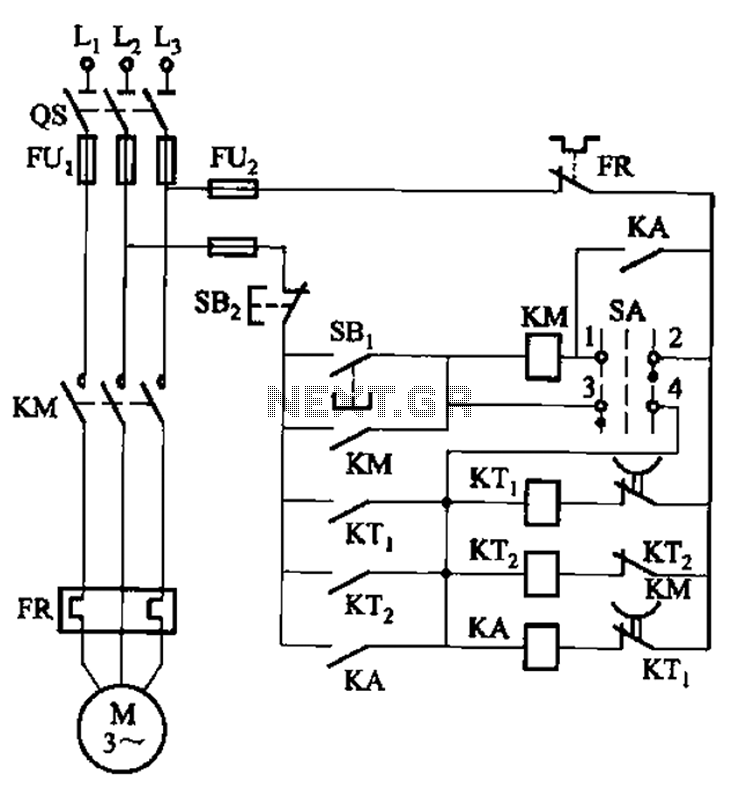
The circuit illustrated in Figure 3-78 utilizes two relays for automatic control, featuring a more complex line structure. This configuration allows for intermittent motor operation. Additionally, it can operate continuously when switch SA is positioned to the right. The circuit...