
OTL tube amp amplifier production

The 6N5P tube is a versatile component in audio amplifier designs, particularly in configurations that require low output impedance. In a parallel push-pull arrangement, multiple tubes work together to improve efficiency and reduce distortion. Each tube in the setup contributes to a lower overall output impedance, which is critical for driving speakers effectively.
The circuit design includes an output transformer that can be omitted if a dual power supply is implemented. This allows for a more compact design and potentially improves the overall fidelity of the amplifier by reducing the number of components that can introduce noise or signal degradation.
The biasing of the tubes is vital for optimal performance. The use of RP1 and RP2 allows for fine-tuning of the operating point of the tubes, ensuring that they function within their linear range. This adjustment is crucial for achieving the desired sound quality and preventing distortion during operation.
In practical applications, the multimeter serves as a diagnostic tool to monitor the voltage drop across the resistor, which is indicative of the current flowing through the circuit. Setting the drop to 0.2V is a typical procedure to ensure that the tubes are operating correctly and within specified parameters.
Overall, the described circuit configuration with the 6N5P tubes is designed to deliver high-quality audio performance while maintaining simplicity and efficiency in its design. The careful selection of components and the adjustment of biasing resistors play a significant role in achieving the desired audio characteristics.6N5P the output impedance of 400 ohms low resistance tube used as a parallel push-pull, the output impedance of a single tube half, and then two-three-plate and pipe used in pa rallel, the impedance will be further reduced, it can be removed from the output transformer used double supply and reasonable bias position adjustment, can be removed from the output capacitor, the whole circuit is shown in Figure 1-33. The figure shows the operating voltage o RPl between levels. RP2 set maximum resistance for adjusting the final stage and screen flow midpoint output. Multimeter set 1V block were measured and down tube 5 (! Voltage across the resistor, adjust RP1, RP2 so drop across the resistor 0.2V.
Related Circuits
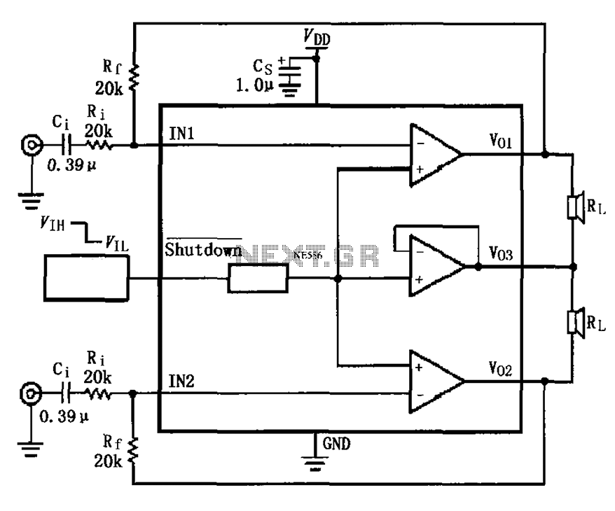
The LM4910 typical circuit is designed for a two-channel amplifier. The left and right channel audio signals are input to the LM4910 (in an MSOP/SO package) at pins 1 and 2. The output signals are delivered from pins 6,...
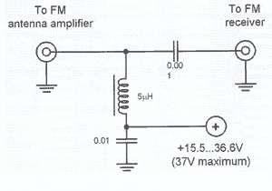
This technique eliminates the need for an additional cable to power the FM antenna amplifier. The RF signal and the DC current that supplies the amplifier utilize the same cable simultaneously. An FM antenna booster circuit diagram can be...
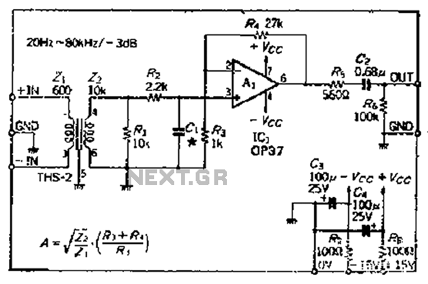
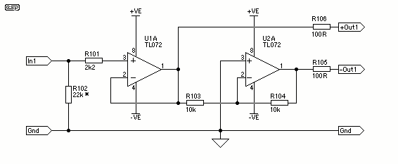
The common mode signal rejection ratio is influenced by the input transformer, which should either be a commercially available or a well-balanced homemade transformer. It is important to note that as frequency increases, the balance may decrease. The transmission...
The first circuit is a simple preamplifier that illustrates the power arrangements for delivering DC to the amplifier via a coaxial cable. The second circuit includes a minor modification to allow the antenna to remain functional for transmitting. The...
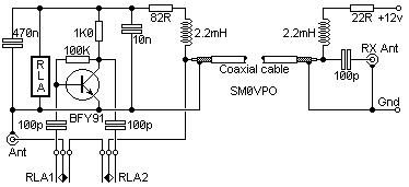
A stereo power amplifier is limited in its output power by two main factors - the impedance of the load and the internal power supply voltage. To obtain more power, one has very limited choices - other than the...
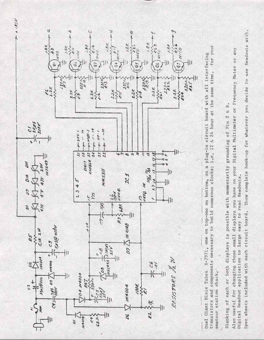
A Burroughs B-7971 Nixie Tube clock was constructed in 1979 during the senior year of high school. The digits measure 2.5 inches in height, enabling visibility from anywhere in the bedroom without the need for glasses. The clock circuit...