
Output 5v / 0.4a small switching power supply circuit diagram

This low-power switching power supply circuit is designed to provide a stable 5V output at a current of 0.4A. It is particularly suitable for applications requiring efficient power conversion with minimal energy loss. The circuit employs a soft-switching technique, which helps to reduce electromagnetic interference (EMI) and improve the overall efficiency of the power supply.
The circuit typically consists of several key components including a switching element (such as a MOSFET), an inductor, a diode, and a capacitor. The MOSFET operates in a switching mode, rapidly turning on and off to regulate the output voltage. The inductor stores energy during the 'on' phase and releases it during the 'off' phase, smoothing the output current. A diode is used to prevent reverse current flow, ensuring that the energy stored in the inductor is directed towards the load.
Additionally, a feedback mechanism is often integrated into the circuit to monitor the output voltage and adjust the switching frequency accordingly. This feedback loop enhances the stability of the output voltage under varying load conditions.
The transformer saturation soft-switching technique specifically allows for lower voltage stress on the switching components, extending their lifespan and improving reliability. This is achieved by ensuring that the switching occurs when the voltage across the MOSFET is minimal, thereby reducing the switching losses.
Overall, this circuit is ideal for low-power applications where efficiency and compact design are crucial, such as in battery-operated devices, portable electronics, and low-power industrial equipment.Is shown in the output is 5V / 0.4A low-power switching power supply circuit, the circuit can be used to make transformer saturation soft-switching circuit.
Related Circuits
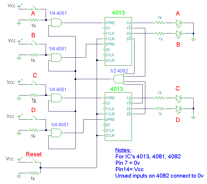
This design utilizes four integrated circuits (ICs) and features four input circuits with four independent outputs, along with a single master reset switch. The outputs are configured with light-emitting diodes (LEDs), which can be modified to control lamps or...
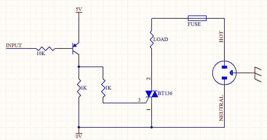
A circuit was designed to function as a light dimmer, utilizing a BT136 SCR and an MOC3022 optocoupler. However, the circuit did not operate as intended. The circuit aims to control the brightness of a light source through phase control...
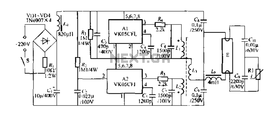
Figure 289 illustrates the VK05CIl, an ASIC produced by STMicroelectronics (ST) designed to operate low-power compact fluorescent lamps ranging from 5 to 15W. The VK05CFI is engineered to drive approximately 23W low-power compact fluorescent lamps using high-pressure composite bipolar...
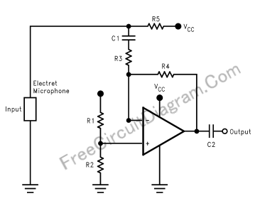
This document presents a schematic diagram of an electret microphone pre-amplifier utilizing the LMV721 operational amplifier. The LMV721 is chosen for its low noise and low power characteristics. The electret microphone pre-amplifier circuit is designed to amplify the weak audio...
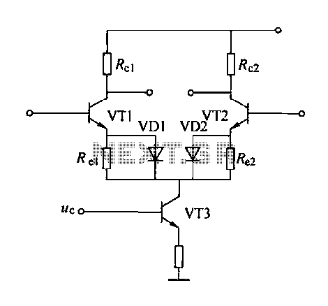
A controllable gain amplifier functions as an automatic gain control circuit within the execution unit. The primary methods for controlling the amplifier's gain involve two approaches: one is by adjusting certain parameters of the amplifier itself, such as emitter...
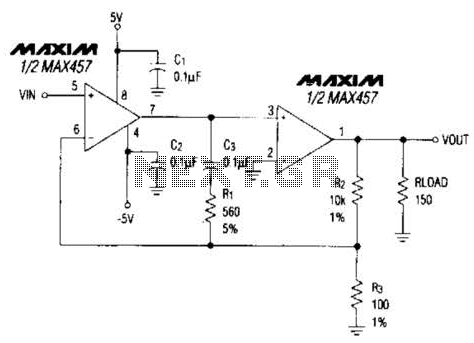
A composite amplifier can be constructed that offers high gain, wide bandwidth, and good DC accuracy by cascading the sections of a dual video amplifier and incorporating two suitable phase compensation components. The operational amplifier drives a 150-ohm load...