
Overheat Detector Alarm/Switch

The LM35 temperature sensor is a well-known device used for temperature sensing applications. It operates over a temperature range of -55°C to 150°C and outputs a voltage that is directly proportional to the temperature in degrees Celsius. This characteristic makes it particularly useful for interfacing with analog-to-digital converters (ADCs) and microcontrollers.
In a typical application circuit using the LM35, the sensor is powered by a voltage supply, usually between 4V and 30V. The output voltage of the LM35 is 10 mV per degree Celsius, allowing for straightforward interpretation of the temperature reading. For instance, at 25°C, the output voltage would be 250 mV.
The circuit may include additional components such as resistors for signal conditioning, capacitors for noise filtering, and operational amplifiers to amplify the output signal if required. A common configuration involves using a non-inverting amplifier to boost the output voltage, which can improve the resolution of the temperature reading when interfaced with an ADC.
To ensure accurate readings, the circuit should also implement proper thermal management. This can include minimizing thermal lag by placing the sensor in a location that accurately reflects the temperature of the environment being monitored. Additionally, the PCB layout should consider the placement of the LM35 to avoid interference from other components and ensure a stable ground reference.
In summary, the LM35 temperature sensor circuit is designed to provide precise temperature measurements with a simple linear output, making it suitable for a wide range of applications in environmental monitoring, HVAC systems, and industrial processes. Proper design considerations, including power supply, signal conditioning, and thermal management, are crucial for achieving reliable performance.At the heart of this circuit is a precision integrated temperature sensor type LM35 (IC1), which provides an accurately linear and directly proportional o.. 🔗 External reference
Related Circuits

This schematic diagram illustrates a water level sensor, detector, and monitor circuit. An alarm is also integrated into this circuit. It is designed to detect any fluid with a resistance below 900K ohms. The water level sensor circuit typically employs conductive...
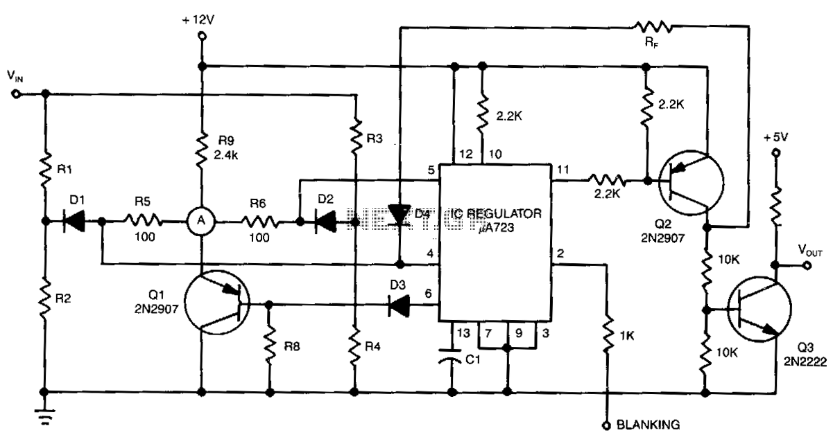
The detector circuit compares the output voltage of two separate voltage dividers with a fixed reference voltage. The resultant absolute error signal is amplified and converted to a logic signal that is TTL compatible. The described detector circuit serves as...
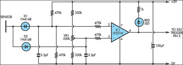
It is well known that simple everyday activities, such as walking on a carpet or moving in a chair, can lead to the accumulation of static charge in the body, sometimes reaching thousands of volts. This circuit is designed...

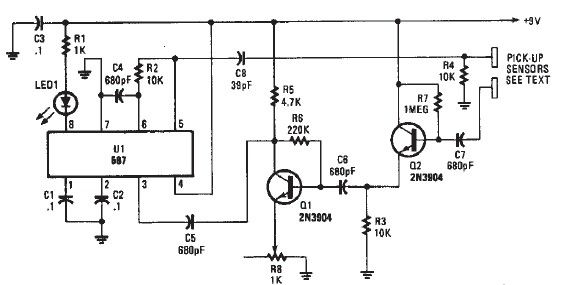
The following circuit is an enhanced version of the original Lightning Detector designed to operate on a 5-volt supply. This updated circuit incorporates a refined RF section with a single resonance near 300 kHz and increased sensitivity. The use...
A simple proximity detector electronic project can be designed using this schematic circuit. This project utilizes a tone decoder integrated circuit (NE567), which provides a signal with a frequency of approximately 100 kHz. When an object is placed near...

In Fig.1 see a DC current sensing switch, in which the current is applied from an 8 to 16 Volt supply. The R1 value is chosen so that it generates roughly 100 mV at the required trip current. In...