
Water Level Sensor/Detector/Monitor With Alarm

The water level sensor circuit typically employs conductive probes or electrodes that are placed at various levels within a tank or reservoir. When the water level rises to a certain point, the conductivity between the probes changes, triggering the sensor. The circuit can employ a comparator or a microcontroller to monitor the resistance values of the fluid.
In this specific design, the alarm system is activated when the resistance of the fluid drops below the specified threshold of 900K ohms. This could indicate the presence of water or another conductive liquid, signaling the need for attention. The alarm can be a simple buzzer or a more complex sound system, depending on the application requirements.
Power supply for the circuit is typically provided through a DC source, ensuring that the sensor and alarm components operate reliably. Additional components such as resistors, capacitors, and possibly a relay may be included to condition the signal and control the alarm output effectively.
The schematic may also include safety features, such as diodes to prevent back EMF from damaging sensitive components, and filtering capacitors to stabilize the power supply and reduce noise. Overall, this circuit serves as a practical solution for monitoring water levels in various applications, including industrial tanks, aquariums, or home water systems.This schematic diagram shows a water level sensor/detector/monitor circuit. An alarm is also featured in this circuit. Any fluid with a resistance under 900K.. 🔗 External reference
Related Circuits
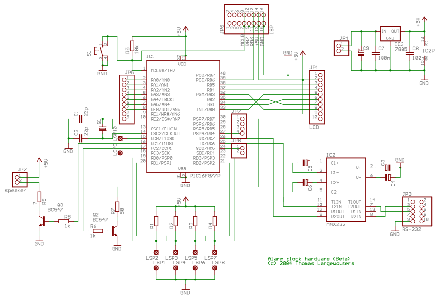
This project outlines a digital clock featuring an alarm function, utilizing a PIC16F877 microcontroller to achieve an accurate 1-second delay with Timer0 through Roman's zero error method. The time is displayed in large font on a 4G—20 character LCD,...
The controller consists of a liquid level sensor, a trigger controller, and a step-down rectifier circuit. The water level detection poles labeled a, b, and c form a bias circuit, functioning as a water level detector with components W1,...
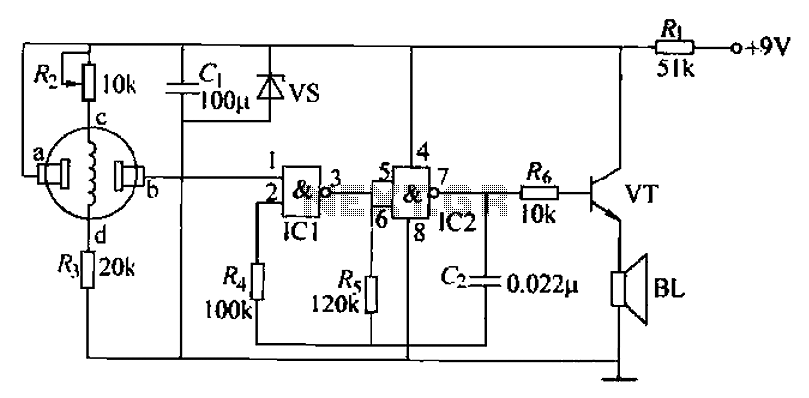
The combustible gas alarm circuit is depicted. The circuit comprises a gas sensor, a multivibrator, and audio output components. The multivibrator is implemented using two NAND gates within an integrated circuit (IC2) and includes external resistive and capacitive components....
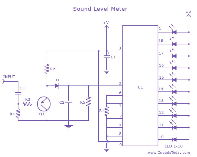
A sound level meter circuit with a diagram and schematic using the IC LM3915, which is an audio level measurement chip. It is used to display the sound level of an amplifier or a microphone. The sound level meter circuit...
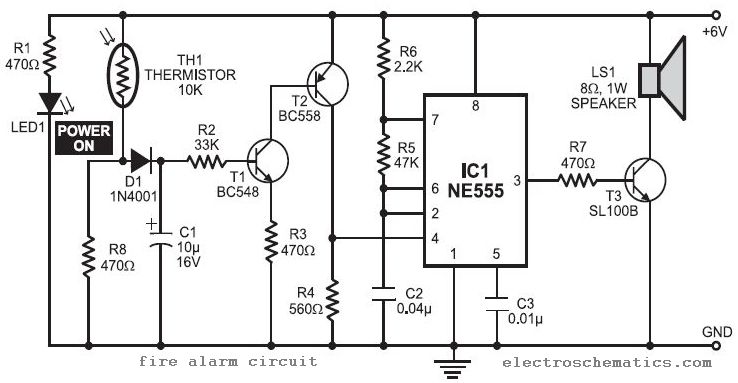
In this fire alarm circuit project, a thermistor functions as the heat sensor. When the temperature rises, its resistance decreases, and conversely, when the temperature falls, its resistance increases. Under normal conditions... In this fire alarm circuit, the thermistor is...
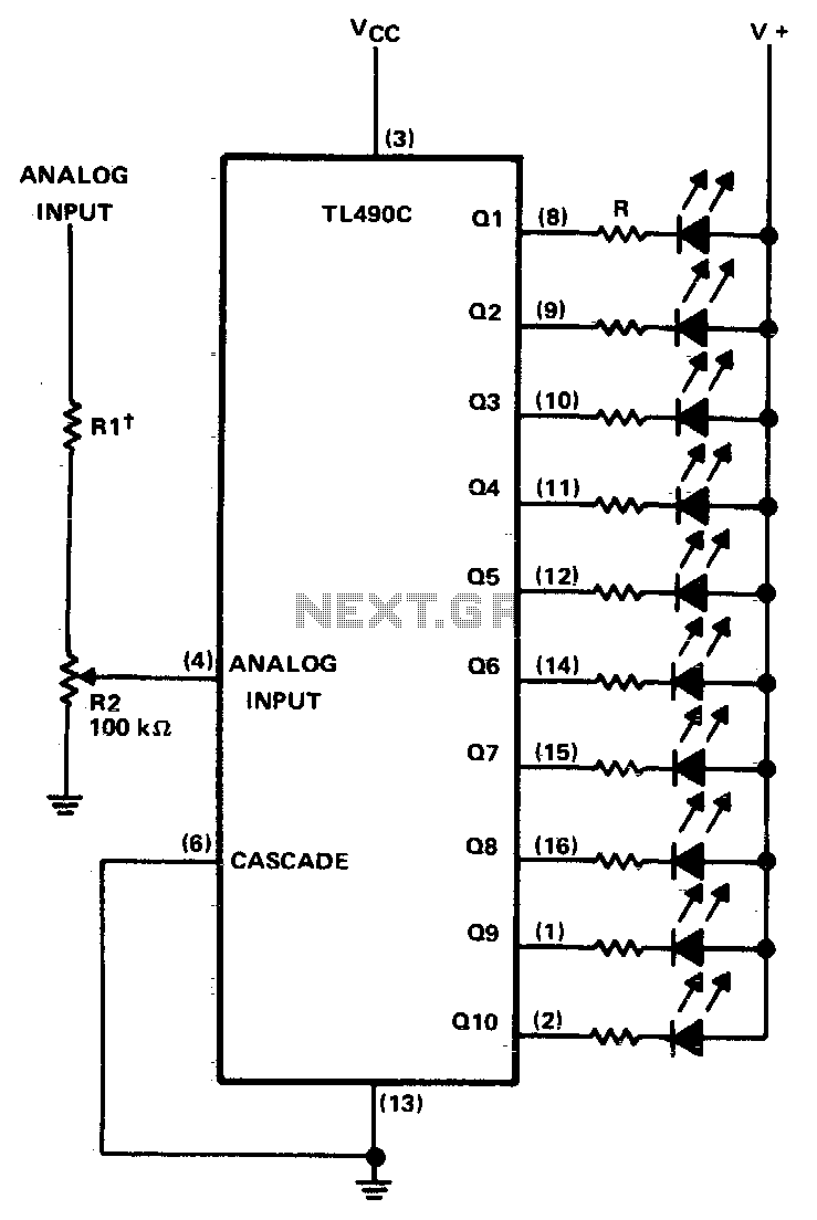
This ten-step adjustable analog level detector is capable of sinking up to 40 milliamperes at each output. The voltage range at the input pin should range from 0 to 2 volts. Circuits of this type are useful as liquid-level...