
Overtone crystal oscillator

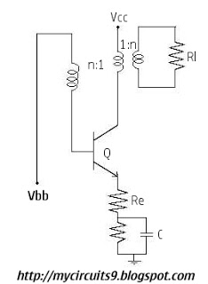
The oscillator circuit is specifically tailored to utilize overtone crystals, which are designed to resonate at higher frequencies, typically in the third and fifth overtone modes. These modes allow for efficient frequency multiplication, enabling the oscillator to generate signals within the specified frequency range of 20-100 MHz.
The core component of the oscillator is the overtone crystal, which is characterized by its high Q factor, providing stability and low phase noise. The tuned circuit, which consists of inductors and capacitors, plays a crucial role in determining the operating frequency. By adjusting the values of these reactive components, the circuit can be finely tuned to achieve the desired frequency output.
In designing the oscillator, attention must be given to the load capacitance and the series resistance of the crystal, as these factors influence the performance and efficiency of the oscillator. Additionally, the circuit may incorporate feedback mechanisms to enhance stability and minimize drift over time.
Power supply considerations are also critical, as the oscillator must operate within specified voltage and current limits to ensure reliable performance. The output stage of the oscillator can be designed to drive various loads, depending on the application, whether it be for RF transmission, signal generation, or clocking applications in digital circuits.
Overall, this oscillator design is suitable for applications requiring precise frequency generation in the specified MHz range, leveraging the properties of overtone crystals to achieve high performance and reliability.This oscillator is designed for overtone crystals in the 20-100 MHz range operating in the third and fifth mode. Operating frequency is determined by the tuned circuit.
Related Circuits
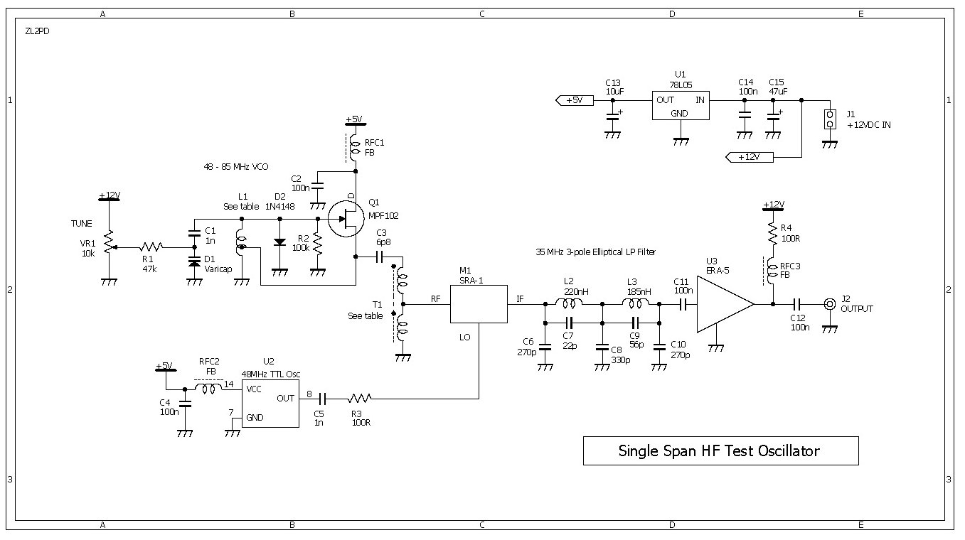
This compact RF oscillator operates across the entire frequency range of 0.4 to 30 MHz in a single sweep of the dial, featuring a terminated 50-ohm output of more than 300 mV throughout the HF band. Unlike most signal...
The 2N4416 JFET exhibits very low harmonic distortion, making it ideal for smooth oscillation in electronic circuits. It is particularly effective in applications where minimal harmonic content is essential for high-performance mixer circuits. Below is the circuit diagram of...
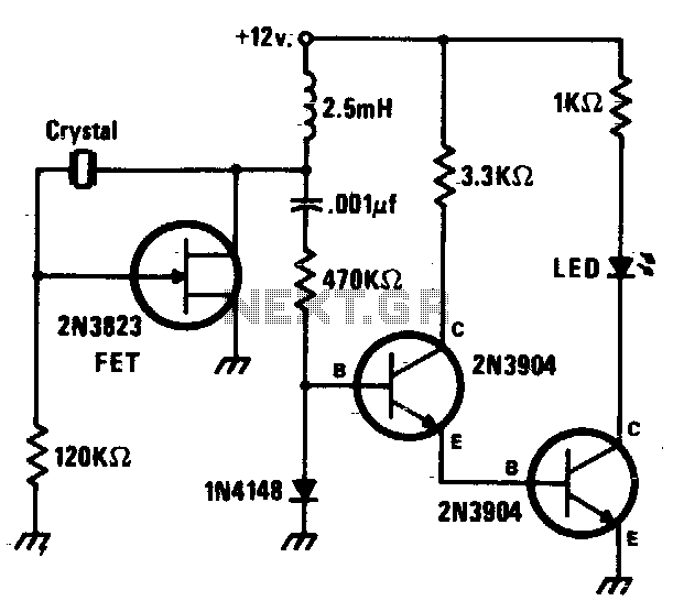
This circuit is a simple Pierce oscillator with an LED go/no-go display. The checker works best with crystals having fundamental frequencies in the seven to eight megahertz range. The Pierce oscillator circuit is a popular choice for generating high-frequency signals,...
The Wien-bridge oscillator consists of an operational amplifier (OA) in a non-inverting configuration with a gain of 1 + R2/R1 and an RC feedback network. The Wien-bridge oscillator is a type of electronic oscillator that generates sine waves. It employs...
Initially, there is a voltage Vc on capacitor C1 that is greater than Vbb - Vg, where Vg is the cutoff base-emitter voltage and g represents Gamma. Consequently, the transistor is in the off state, and capacitor C1 discharges...
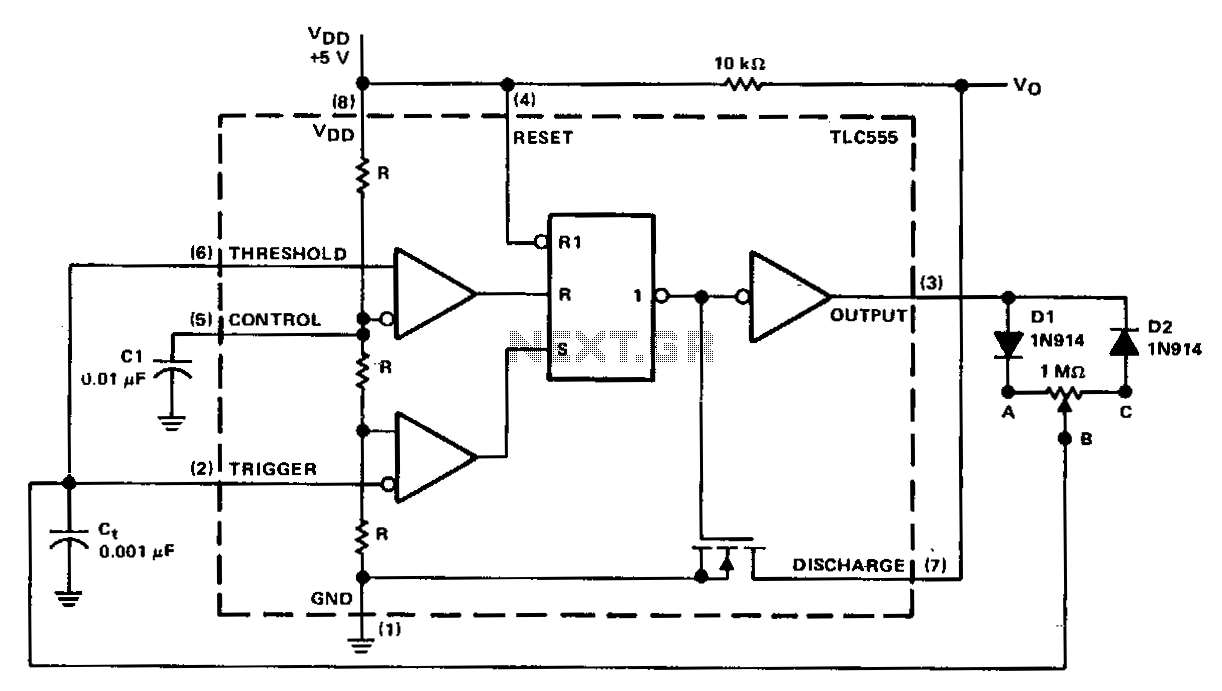
In a basic astable timer configuration, timing periods 11 and 12 are not independently controlled. This lack of control complicates the maintenance of a constant period, T, when either 11 or 12 is varied. In this circuit, the charge...