
OverUnity Lead Acid Battery Switching Self Battery Charging
Warning: Undefined array key "extension" in /var/www/html/nextgr/view-circuit.php on line 477
Deprecated: strtolower(): Passing null to parameter #1 ($string) of type string is deprecated in /var/www/html/nextgr/view-circuit.php on line 477

The described circuit utilizes a 555 timer as the core component for oscillation, which is essential for charging applications. The timer's ability to self-oscillate at a minimum voltage of 3V allows for flexibility in various battery charging scenarios. The inclusion of a relay across a low-value resistor not only provides short circuit protection but also regulates the current, ensuring safe operation while charging the supercapacitor.
When implementing the switching mechanism, the choice between an N-Type and P-Type MOSFET can significantly affect the circuit's complexity. The N-Type MOSFET is generally favored for its efficiency in handling higher currents and voltages, while the P-Type MOSFET may require additional considerations for pin configuration, which is often not clearly documented in datasheets.
The application of a PIC12F629 microcontroller introduces advanced control over the charging process, allowing for precise timing and operational parameters. The specified switching cycle of 55 microseconds on and 1 second off provides a balanced approach to charging, minimizing heat generation while maximizing efficiency. This microcontroller approach not only reduces the overall component count but also enhances the reliability of the circuit.
For the proposed battery bank of 60Ah/24VDC, the design of inductors L1 and L2 must be recalibrated to accommodate the desired charging time of 6 to 8 hours. The inductance values will need to be calculated based on the required current and the characteristics of the battery being charged. Furthermore, the inverter system's capacity to drive various loads after full battery charge must be considered, ensuring that the inverter's specifications align with the energy requirements of the connected devices.
In summary, the circuit design must integrate efficient components, appropriate control mechanisms, and careful consideration of load requirements to achieve optimal performance in battery charging applications.The only way to know how fast a particular battery can recharge itself is to put it under load, vary the switching frequencies, on / off times, & then plot the results. A circuit drawing 0. 5 Amps at 12 Volts will charge a battery slowly, so increasing the power used to 2 amps or more is something you should be looking at if you want a fast charger
. The 555 needs at least 3 volts before it will begin to self oscillate. Once the 555 circuit starts to oscillate, the power switching will take over & will continue to charge the supercap until it is fully charged. The relay placed across the low value resistor is used as a current regulator or short circuit protection circuit.
Its cheap & effective. The switching part of the circuit can be constructed using a N-Type Mosfet but it makes life much harder, so just get the right parts if you are going to try this. Also I could not find a direct pinout for the P-Type mosfet IRF5305. The data sheets forgot to tell us what the pins were. I have already build a battery desulator base on PIC12F629 using 8 pin micro-processor could recover even 0.
9v maintenance free Lead-acid battery(2Ah) to 12volts in 2days. Even some of circuit people build tend to use a "lead-acid battery" when they noticed a rise in battery voltage, the creator of circuit thought they have have created OU device. A real OU device should be running on ultra-caps or nimh battery where the internal self-discharge rate is higher.
If there is voltage increase in cap or nimh then it could be the real deal without using any input batteries. The switching cycle is 55us on with 1s off in infinte loop for programming the PIC12F629. This is just a replica of 555 base found in instructables site. I did micro-processor version merely to lower component count. Please look at this link where i posted full finding around 2 years ago and even mentioned the 2 ways to check a 12volt battery(If the internal resistance is being lowered) while it`s being desulfated or after desulfated.
HI, magpwr i have see your circuits and some explanation about your circuits you have built and tested as so far in the low current and the standard voltage, i have some question on it about this, and i need your advice on this questions. 1. the circuits you build is low current and the L1, value of inductor its 1mH, and the L2, 220uH, if this two component is i change to any other value for charging the battery of 60aH/24VDC battery bank means, how to i design this coil for reach that current to have charge in the 6.
or 8 hours duration charging time, can you give some advice on this, please. 2. my system battery bank is 24v/60ah and my planing is to drive the lamp, dvd, computer, and etc, atleast for the 3. to 4 hrs time, and i want to connect with 1000watt inverter system for drive this load after the full charge the battery bank of i mentioned.
🔗 External reference
Related Circuits
Charge your iPod without connecting it to a computer! Using the USB port on your computer to charge your player's batteries is not always practical. To facilitate the charging of an iPod without the necessity of a computer, a dedicated...
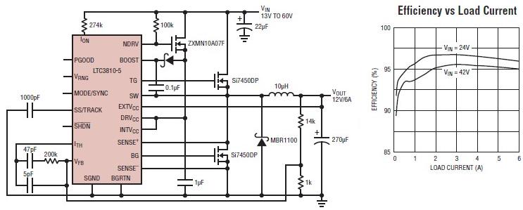
The LTC3810-5 synchronous step-down switching regulator controller allows for the design of a straightforward 12-volt switching power supply electronic project with minimal external components. This controller can directly reduce voltages from up to 60V, making it suitable for telecommunications...
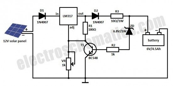
This is a solar charger circuit designed to charge Lead Acid or Ni-Cd batteries using solar energy. The circuit captures solar energy to charge the batteries. The solar charger circuit typically consists of several key components, including a solar panel,...
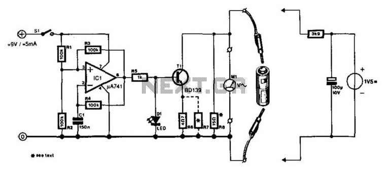
A designer often needs to know the internal resistance value of a battery. Many testers provide a relative indication of this value, but it is seldom expressed in ohms. The current tester can, in principle, provide this information. The...

R1 controls the trip-point of the circuit. adjust it accordingly. to reverse the logic (have the led light up when the battery has at least X amount of power,) connect the led to ground through R4. More: all resistors...
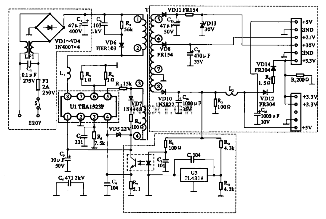
The East Shi IDS-2000F STB switching power supply circuit primarily consists of an AC input circuit, a switching oscillation circuit, an output circuit, and a secondary steady voltage control circuit. The AC input circuit includes a switch (S), fuse...