
12v high/low battery monitor

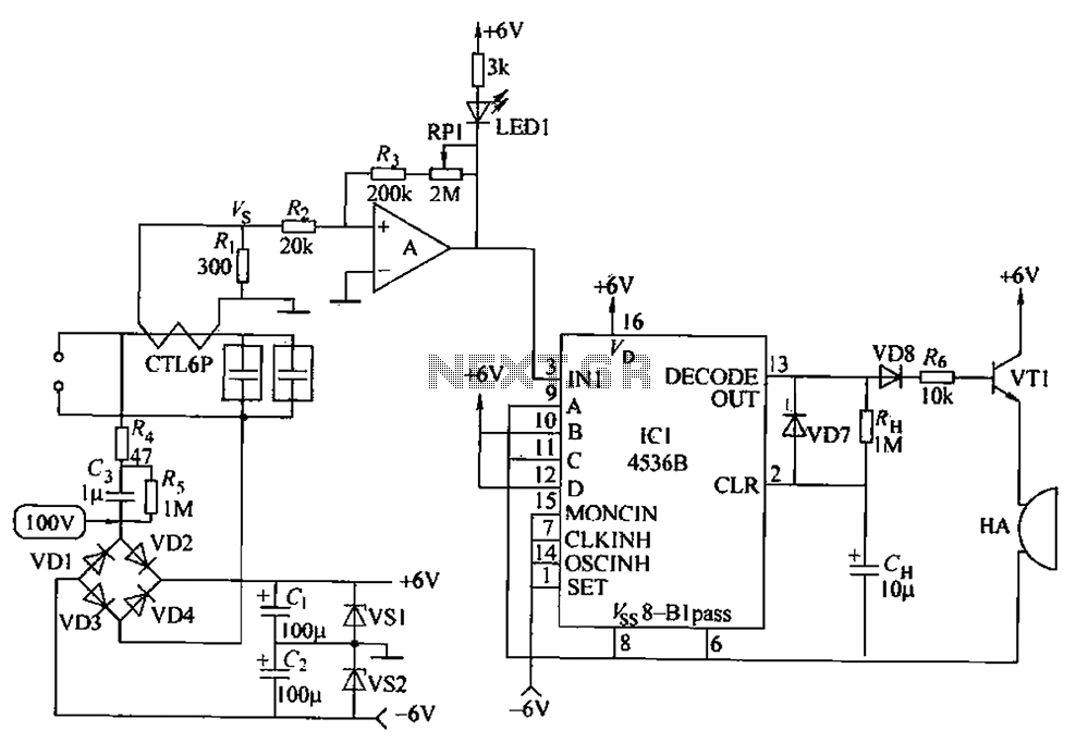
The circuit described employs a resistor (R1) to set a specific voltage threshold known as the trip-point. This trip-point is crucial for determining when the circuit will activate or deactivate a connected load, such as an LED. The adjustment of R1 allows for calibration of this threshold, enabling the user to fine-tune the circuit's sensitivity to the input voltage, which in this case is derived from a battery.
To modify the logic of the circuit so that the LED illuminates when the battery voltage exceeds a specified level (X), the LED should be connected to ground through another resistor, R4. This configuration creates a condition where the LED will turn on when the voltage across R4 is sufficient to forward bias the LED, indicating that the battery voltage is above the desired trip-point.
Both R1 and R4 are specified to have tolerances of 5% or 10%, ensuring that the circuit maintains a degree of reliability and predictability in its operation. The power rating of 1/4-watt for these resistors suggests that they are suitable for low-power applications, which is typical in battery-operated devices.
In summary, the combination of R1 for trip-point adjustment and R4 for LED control provides a fundamental mechanism for monitoring battery voltage levels, with the potential for user-defined thresholds and clear visual feedback through LED illumination.R1 controls the trip-point of the circuit. adjust it accordingly. to reverse the logic (have the led light up when the battery has at least X amount of power,) connect the led to ground through R4. all resistors are 5 or 10 percent tolerance, 1/4-watt 🔗 External reference
Related Circuits
The circuit principle involves using a current transformer for current sensing due to the large AC power load of computers. This setup detects whether there is current in the power line, enabling the determination of its status. The LM393...

This is the schematic diagram of a 15W inverter circuit. The circuit is based on a PNP power transistor such as the TIP32 and other similar transistors. This inverter produces a square wave output, which may cause some noticeable...
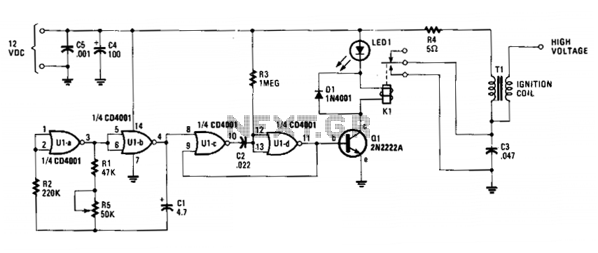
The circuit is fundamentally an auto ignition coil paired with a set of points that perform a similar function. It employs a pulsing circuit constructed from a single CMOS NOR integrated circuit (U1) to open and close relay contacts,...

To reduce the resonant frequency and obtain useful signals, washers were placed on a bolt along with nuts for experimentation. An oscilloscope with FFT was utilized to adjust the weight at the tip of the film until frequencies around...
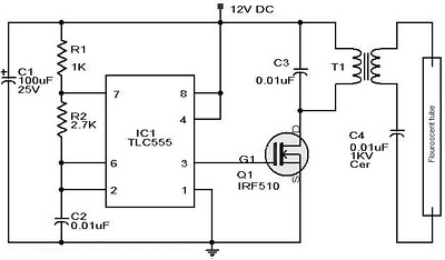
Whenever there is a need for battery-powered lighting, such as for camping, solar-powered cottages, cars, boats, planes, or emergency situations, fluorescent lamps are highly appealing. They are significantly more efficient than incandescent lamps, producing much more light for less...

This circuit is designed to protect a computer monitor from overheating and is recommended for use with power users' monitors. Most CRT-type computer monitors tend to fail due to excessive heat, which can cause the rear of the monitor...