
Internal Resistance Battery Tester

The described circuit operates on the principle of measuring the internal resistance of batteries by employing a controlled load and an alternating current (AC) measurement technique. The circuit consists of a square-wave generator (IC1) that drives a current source (T1) to modulate the load current applied to the battery under test. This modulation creates an AC voltage drop across the internal resistance, which is then measured using a standard AC voltmeter.
Resistor R8 serves as the primary load for the battery, and its specific value of 1.5 ohms is critical for 1.5-V batteries, ensuring that the load current remains within acceptable limits for accurate measurements. The AC voltmeter, connected in parallel with the battery, provides a direct reading of the voltage drop, which is multiplied by a factor of 10 to yield the internal resistance in ohms.
The circuit also includes a calibration feature, allowing the user to set the tester for accurate readings. The auxiliary circuit, comprising a 1.5-V supply and an electrolytic capacitor, simulates an ideal voltage source for calibration purposes. The internal resistance of this source is represented by a 3.9-ohm resistor, which allows for the determination of the correct value for R7 when the voltmeter reads 0.39 V.
The design ensures that the tester is versatile for different battery types, with provisions to adjust the load current for higher voltage batteries like 9-V. This adjustment is achieved by changing the values of resistors R6 through R8, making the circuit adaptable for various applications while maintaining measurement accuracy. The inclusion of LED1 provides a visual indication of the supply battery status, enhancing the usability of the tester in practical scenarios. Overall, this circuit design effectively measures internal resistance, providing valuable insights into battery health and performance. A designer often needs to know the value of the internal resistance of a battery. Quite a few testers gi ve a relative indication of the value, but this is seldom in ohms. The present tester can, in principle, provide that information. The basic idea behind it is to load the battery with a varying current, so as to cause an alternating-voltage drop across the internal resistance that can be measured at the battery terminals. Provided that current variations are regular and constant, the voltage drop is directly proportional to the internal resistance.
Choose the variation of the current carefully to read the value of the internal resistance directly on the scale of an ac voltmeter. The load current is varied with the aid of a current source, T1 in the diagram, which is switched on and off by square-wave generator IC1.
The chosen switching frequency of 50 Hz ensures that the ac component at the battery terminals can be measured by a standard ac voltmeter (universal meter). The battery is loaded constantly by R8, which has a value of 1.5 for 1.5-V batteries, shunted by the ac voltmeter.
The indicated voltage times 10 is the value of the internal resistance of the battery. When the battery under test is flat or if the supply battery is flat, no current flows and the meter will read zero. It would then appear as if the battery under test is an ideal type—without internal resistance. A flat supply battery is indicated if Dl does not light. You can ascertain that the battery under test is flat by measuring the direct voltage across its terminals.
The load must be left connected, of course, otherwise the emf is measured and this may well be 1.5 V—even if the battery is flat. The tester is calibrated with the aid of the auxiliary circuit (shown at the extreme right in the circuit diagram).
The 1.5-V supply and electrolytic capacitor form a virtually ideal voltage source, of which the 3.9- resistor forms the internal resistance. With this source connected across the output terminals of the tester, a suitable value should be ascertained for R7.
That value is found when the ac voltmeter shows 0.39 V. Notice that this procedure is not the same for all measuring instruments: the alternate use of the digital and a moving coil meter, for instance, is not feasible. The tester is intended for 1.5-V batteries. The load current is fairly high: about 100 mA through R8 and around 170 mA through Tl. For 9-V batteries that current is too high: the current should then be reduced by taking greater values for R6 through R8.
Related Circuits
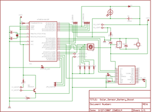
The project involves enhancing the Botanicalls system by integrating a solar panel that functions as both a light sensor and a battery charger for each plant. The complete circuit schematic is provided above, along with detailed images illustrating the...
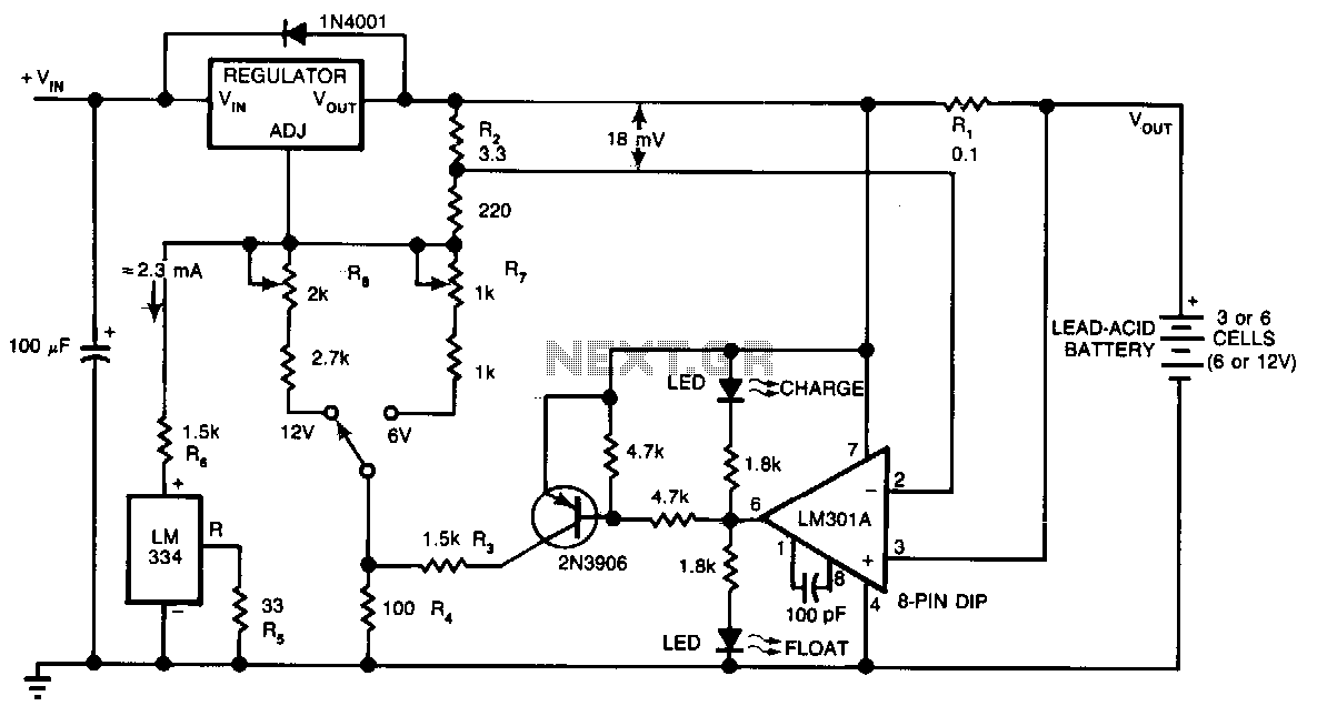
This circuit provides an initial voltage of 2.5 V per cell at 25°C to rapidly charge a battery. The charging current decreases as the battery charges, and when the current drops to 180 mA, the charging circuit reduces the...
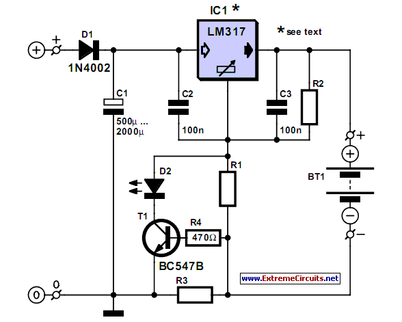
A simple NiCd charger can be constructed using readily available components and an economical LM317 or 78xx voltage regulator. The design incorporates a current limiter made up of resistor R3. The proposed NiCd charger circuit utilizes an LM317 or a...

This is a simple servo tester designed to thoroughly evaluate the capabilities of nearly any modern servo. It features two pushbuttons, labeled CENTRE and SWEEP, along with a potentiometer that functions in the following manner: The servo tester circuit is...
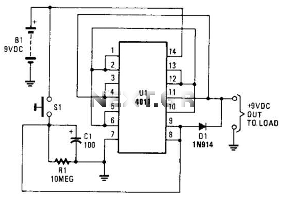
This battery saver circuit can automatically turn off a small piece of test equipment after a desired period of time, allowing for worry-free operation in a workshop environment. The circuit utilizes a CD4011 integrated circuit (IC) to function as...
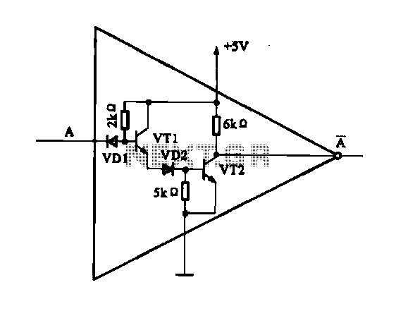
The internal structure of the DTL inverter circuit (M5936P) is composed of inputs with diodes and transistors for signal processing, powered by a +5V supply. When the input terminal A is at a high level (digital 1), diode VDI...