
panasonic wv f15 camera

To activate the tally light on an F15 camera viewfinder in the absence of a Camera Control Unit (CCU) or Remote Control Unit (RCU), a direct wiring approach can be employed. The tally light serves as a visual indicator to inform the operator when the camera is actively recording or transmitting.
To implement this solution, first identify the pin configuration of the viewfinder's connector. The tally light typically requires a power source and a signal input to function correctly. A common method involves connecting the tally light directly to the camera's power supply, ensuring that the voltage levels are compatible with the light's specifications.
Next, the signal input for the tally light can be derived from the camera's recording status. This can be achieved by tapping into the camera's internal circuitry, specifically the output that indicates when the camera is in record mode. It is crucial to isolate this signal to prevent any interference with the camera's normal operation.
When wiring the tally light, use appropriate gauge wires to handle the current without overheating. Additionally, ensure all connections are secure and insulated to prevent short circuits. Testing the setup before finalizing the installation is advisable to confirm that the tally light operates as intended.
In summary, while the absence of a CCU or RCU complicates the activation of the tally light on an F15 camera viewfinder, a direct wiring solution can be implemented by connecting the tally light to the camera's power supply and recording status output. Proper attention to electrical specifications and safety precautions is essential for successful operation.How to make the tally light work on the F15 camera viewfinder when you don`t have the CCU/RCU.. 🔗 External reference
Related Circuits
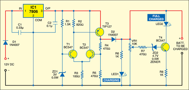
There is no need to be disappointed the next time your digital camera displays a low battery indication during a picnic trip. Simply connect this digital camera adapter to the cigarette lighter outlet of your car and link the...
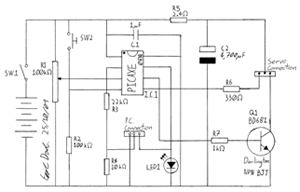
This project involves creating a programmable camera controller using basic hand tools and a digital camera. By utilizing components that are commonly found at home, the overall costs can be minimized. A servomotor can be repurposed from a radio-controlled...
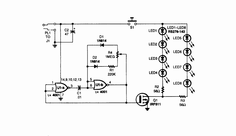
An infrared (IR) illuminator designed for night-vision television cameras and scopes. This device employs light-emitting diodes (LEDs) and an astable oscillator to manage the switch, duty cycle, and overall effective IR illumination output. The IR illuminator functions by emitting infrared...
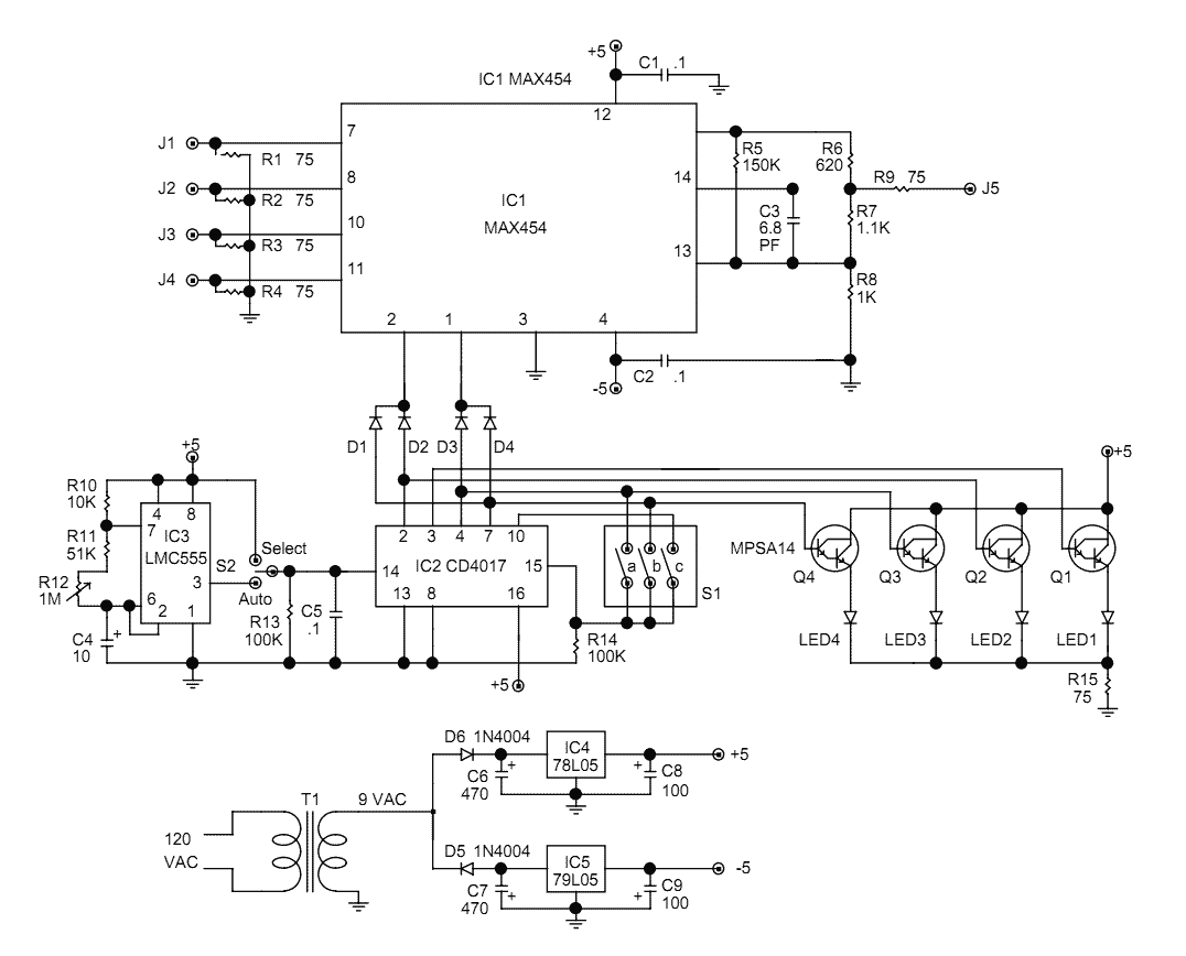
The video switcher described here can display the output of two, three, or four cameras on a single monitor. The number of cameras is set by a DIP switch on the circuit board. That feature avoids blank displays if...
The circuit consists of a light metering circuit and a flash circuit, as illustrated in the accompanying image. It is designed for use with integrated cameras such as POPTICS, Franka X-500, and WIZEN-860S. The circuit includes the following components:...
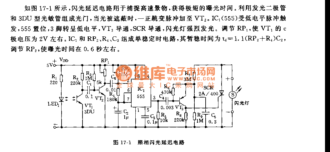
As shown in figure 17-1, the camera flash delay circuit is designed to capture high-speed scenes, allowing for very short exposure times. The light gate consists of a luminous diode and a 3DU type photosensitive tube. When the light...