
Programmable time-lapse camera controller

This programmable camera controller project offers a practical and engaging way to explore electronics and coding. The integration of a servomotor with a digital camera allows for automated photography, which can be particularly useful for creating time-lapse videos. The choice of components, particularly those rated for 6 volts or higher, ensures compatibility and reliability in operation.
The assembly process begins with the design of the electronic circuit on a breadboard, allowing for easy modifications and testing before finalizing the layout on a printed circuit board. The use of a flow diagram during the software development phase aids in clarifying the logic and functionality of the code, which is essential for controlling the servo and timing the camera's shutter.
When constructing the adapter plate, precision is key, as it must securely hold both the camera and the servomotor in the correct alignment. The choice of materials, such as aluminum from scrap, not only keeps costs low but also provides a sturdy base for the assembly.
In outdoor applications, environmental considerations must be addressed. The use of a waterproof enclosure is vital for protecting sensitive components from moisture, while ensuring that the camera lens remains unobstructed. The configuration of the camera settings, such as resolution and flash, also plays a crucial role in the quality of the final output.
The final assembly involves careful soldering of components onto the PCB, with attention to detail in maintaining correct polarity and orientation. Testing the circuit with a multimeter ensures that all components are functioning as intended before sealing the enclosure. This project not only enhances technical skills but also provides an opportunity for creative expression through the art of photography.With a few basic hand tools and a digital camera, this programmable camera controller project is for you. By using components already available at home, costs may be kept to a minimum. A servomotor may be reused from a radio-controlled model and aluminium for the adaptor plate may be acquired from a manufacturer`s scrap bin.
Be sure to ask for permission first. All the suggested electronic bits need to have a 6-Volt rating or greater and may be bought from local retailers. This project combines creating an electronic circuit, building an adaptor plate so that the servo and the digital camera work together, and writing the software code.
Another interesting part of the project is being able to show people your video, produced from the still photographs recorded by this equipment you have created. Choosing the first subject is pretty easy. The author set a camera up in the family room of his own home, when celebrating a birthday. The camera was out of the way and soon forgotten until the video was viewed and resulted in lots of laughs.
To work effectively outdoors, protecting equipment is a little more difficult. For temporary shelter, umbrellas are great otherwise a showerproof container with a clear front should be used. Some food containers may be used but the interior must be kept dry or condensation may cause water droplets to form on cold equipment and lenses not a good environment for electronic gear.
To reduce condensation inside an enclosure you can fill the excess space with dry rags or bubble wrap. Be sure the lens and servo can still work properly. The camera should be set on the lowest resolution and the flash turned off. Make sure the horizon is horizontal and the verticals are vertical this also makes the video look a bit more professional.
Happy time lapsing! When starting to think about the software code, a flow diagram may help explain what waht you want to achieve. Remember there are often many different software solutions: Experiments with coding and components are carried out on a temporary `bread board` before a final design for the program and electronic circuit are decided.
Soldering sockets and hardware is one of the last operations in prototype development. Launch the PICAXE Programmer and create your own test program to check the functions of the LED and servo on the camera controller or copy the `timeLapseTest. bas` program below. `Notes to users are started with an apostrophe ` sign, which is ignored by the programme compiler and are not part of the code sent to the PICAXE IC.
The track side of the PCboard showing tracks cut with a 3 mm drill. For convenience on the prototype, a small component and jumper have been soldered on the track side of the board. In the final version, these parts should be connected on the top of the board. All components are populating the board and it sits on a battery box cover using Blu-tack to hold it on the lid.
The Blu-tack not only holds the circuit board, but provides clearance for the components on the track side. The battery box contains 4 x 2. 4 Ahr AA 1. 2 Volt rechargeable NiMH cells. Check to see you have all the components on the list or suitable substitutes. Where possible, verify with a multimeter to see that all the components work and that their values are correct.
On the track side of the printed circuit (PC) board, cut tracks to isolate the 8-pin IC socket legs. Next solder components such as resistors, jumpers, sockets and headers. Be sure polari 🔗 External reference
Related Circuits
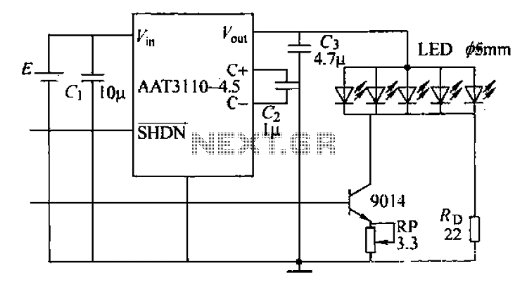
A circuit designed for a phone photo camera flash that delivers a peak current of 200mA. It utilizes the AAT3110-4.5 capacitive charge pump chip to boost and regulate the lithium battery voltage to 4.5V. This voltage powers a series...
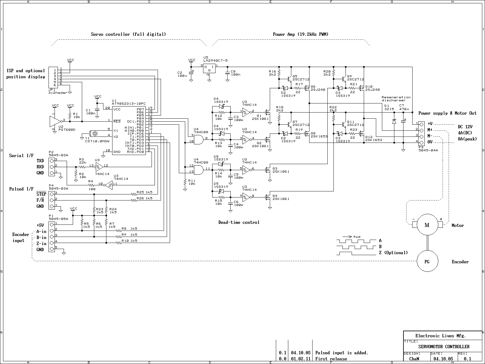
This is an experiment on the closed loop DC servomotor control system (SMC). It will be able to be used for practical use with/without some modifications. The closed loop servo mechanism requires real-time servo operations, such as position control,...

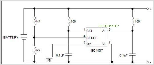
The circuit diagram illustrates a simple stepper motor controller utilizing basic components. The driver circuit employs four SL100 transistors to control the motor windings, along with two NOT gates and one XOR gate to decode the two-bit control logic...
The SC9256 is a phase-locked loop (PLL) integrated circuit designed for digital tuning systems (DTS), featuring built-in 2 modulus prescalers. All functions are controlled through three serial bus lines. These integrated circuits are utilized to configure high-performance digital tuning...
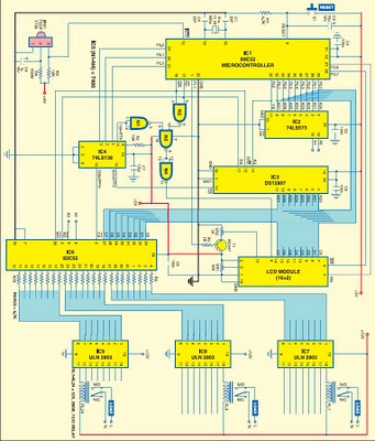
This project is based on the Atmel AT89C52 microcontroller and the Dallas real-time clock (RTC) chip DS12887. It can control and remotely program the switching operations of 24 electrically operated devices, allowing them to be turned on or off...
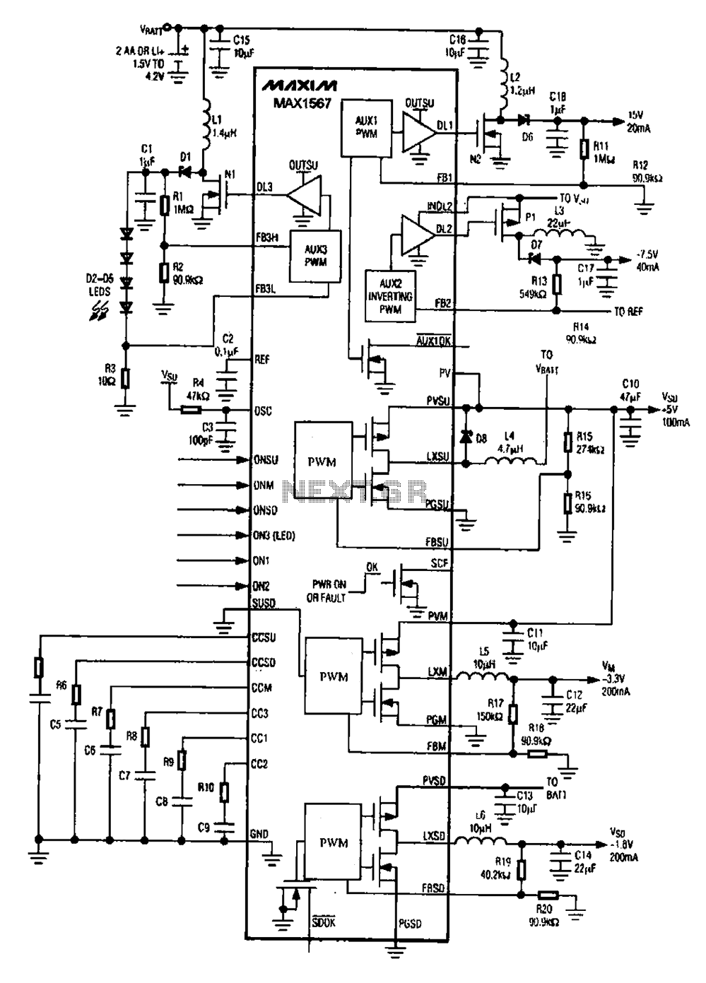
A brush 6-channel camera power supply circuit utilizing the MAX1566/1567. This circuit features a PWM generation system that is divided into six groups, with each group managing a separate channel. The circuit converts the DC voltage from the battery...