
Parallel Computer Bus Description and Pinout

The IEEE-1284 standard provides essential specifications for parallel communication between computers and printers, ensuring compatibility and performance across various devices. The transition from Centronics to IEEE-1284 reflects advancements in data transfer capabilities, accommodating the increasing demands for speed and efficiency in printing tasks. The use of pull-up and series resistors is critical in maintaining signal integrity and ensuring reliable communication, particularly in longer cable runs. The defined levels of compatibility allow manufacturers to design devices that can either utilize basic functionality or take advantage of enhanced features, depending on the intended application. The evolution of the interface from traditional parallel ports to USB and Ethernet connections highlights the ongoing development in printer technology, accommodating modern computing environments and user needs.The IEEE-1284 bus defines a parallel printer bus specification with speeds above 1MBps. IEEE-1284 defines a Point-To-Point asynchronous bi-directional interface. Devices may be either 1284 compatible {the older parallel port devices} or 1284 compliant. The maximum recommended length for a printer cable is 25 feet [up to 32 feet maximum]. Centronic s parallel cables run out to 12 feet. The IEEE1284 cable replaced the `Centronics` cable which is obsolete. An IEEE1284 or Centronics interface will be indicated by the printer having an LPT port [line printer terminal], which normally refers to a parallel port. The LPT port would be a Centronics interface before the mid 1990`s or an IEEE1284 after the mid 1990`s.
However as of 2005 a printer may not have an LPT port, but instead have a USB port and or a Network port with Ethernet. An Ethernet port will normally be found over an RJ-45 jack. To maintain the compatibility with the original Centronics port which uses open collector drivers, pull-up resistors (Rp) are required to transmit logic high levels.
The established common standard resistor values of 2. 2kOhms or 4. 7kOhms. Control and Status lines only require a pull-up resistor (Rp). The data lines and Strobe pin may require a series resistor (Rs) for termination to match the impedance for the 8 bi-directional data lines and the strobe. The series termination value is adjusted so that the addition of the resistor and the driver impedance equal 45 Ohms to 55 Ohms cable impedance.
So a driver IC with a nominal impedance of 15 ohms would require a 33 ohm [ standard value ] resistor to comply with IEEE1284. The 1284 standard defines two levels of interface compatibility, Level I and Level II. The Level I interface is defined for products that are not going to operate at the high speed advanced modes, but need to take advantage of the reverse channel capabilities of the standard.
The Level II interface is for devices that will operate in the advanced modes, with long cables, and at the higher data rates. Compatibility mode; Centronics type operation (PC to Peripheral), providing the original (required) control signaling bits.
These bits include 8 data lines, a Strobe, a Busy, an Acknowledge, a Select, Paper Empty, Fault, Initialize Printer, Select Printer, and a Auto Feed line. Compatibility mode is the basic mode of operation, asynchronous, byte wide operation with a transfer rate of between 50kBps to 150kBps.
Nibble mode; 4 bit data bus (Peripheral to PC), 8 bit data bus (PC to Peripheral); supporting uni-directional printer interfaces. This provides an interface which operates full speed forward and half speed in reverse. The transfer rate is between 50kBps to 150kBps ECP; Extended Capabilities Port. Allowed the PC to send 32 bit data to the port, than letting the port divide up the data into four 8 byte messages, improving system (PC) operation.
Transfer speeds are ten times faster then the previous modes. EPP; Enhanced Parallel Port; Allows high-speed transfers of bytes in either direction. EPP is used with real time controlled peripherals. EPP transfer times are the same as ECP transfer rates. 🔗 External reference
Related Circuits
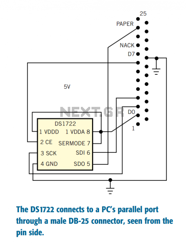
The Dallas Semiconductor DS1722 digital thermometer allows measurement resolution as fine as 0.0625°C in digital form and with linear response. The accuracy specification is only 2°C, but you can improve this figure by careful calibration. Moreover, the accuracy spec...
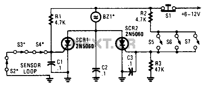
Two SCRs are utilized with two sensor loops. One loop employs series switches, while the other loop employs parallel switches. When a switch is actuated, the SCR is triggered. The alarm is designed to be a non-interrupting type. The circuit...
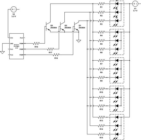
It is noted that the LEDs are not configured in parallel with the transistor. If they were, the LEDs would illuminate when the transistor is off. Instead, the LEDs are connected in parallel before entering the transistor. The transistor...
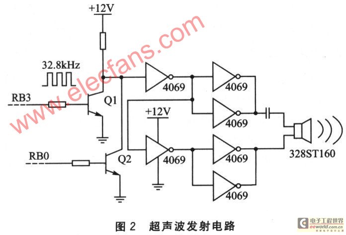
This device is based on the PIC16F628A microcontroller and utilizes a pair of independent ultrasonic transducers for both transmission and reception. It employs the Doppler effect to effectively detect whether someone enters a designated area and can control the...
In the production field, automatic detection of water levels and control is a critical technology for industrial process control, significantly enhancing the level of automation in these processes. In everyday life, water supply has traditionally been managed manually, which...
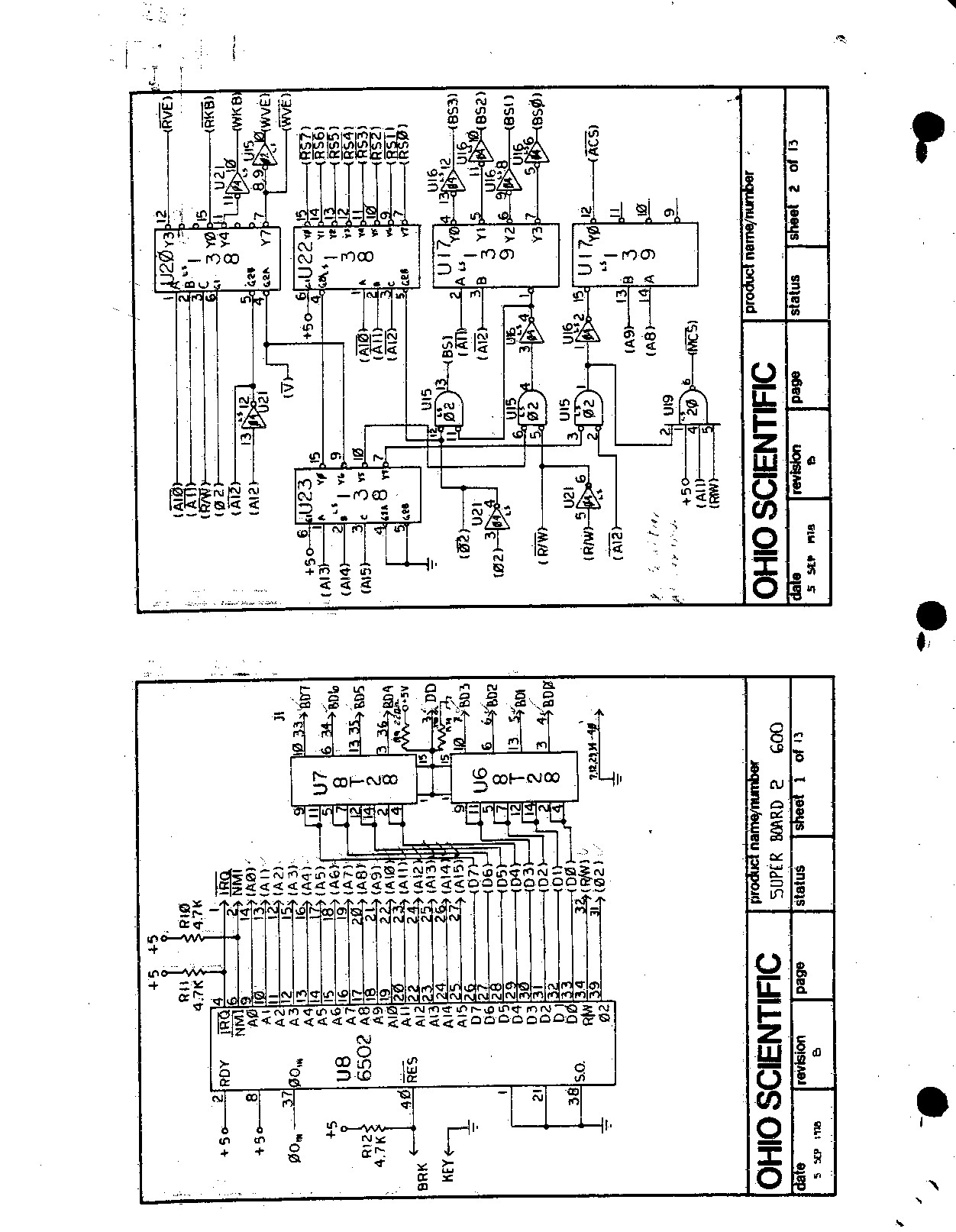
This machine was significant as it was the first real computer, an Ohio Scientific Superboard II, acquired in 1979. It is a 6502-based single-board computer featuring 8K of RAM and BASIC in ROM. The board is entirely self-contained, requiring...