
Parallel Loop Alarm Circuit

The circuit consists of four parallel switches, each representing a distinct monitored position. The configuration allows for redundancy; if any one of the switches is closed, it completes the circuit, leading to the triggering of the silicon-controlled rectifier (SCR1). This SCR acts as a control element that allows current to flow through the alarm system once it is activated.
The alarm system is specifically designed to be non-interrupting, which means that once it is triggered, it will continuously sound until the condition is manually reset or resolved, rather than turning off automatically after a certain period or upon the release of the switch. This feature is crucial in applications where persistent alerting is necessary to ensure that the monitored condition receives immediate attention.
In terms of implementation, the four switches should be connected in parallel to the anode of SCR1, while the cathode is connected to ground. A resistor may be included in series with the alarm to limit the current and protect the circuit components. Additionally, a capacitor can be added across the SCR to manage the turn-off characteristics and prevent false triggering due to transient signals.
The overall design must ensure that the alarm is powered by a stable voltage source, and appropriate ratings for the switches and SCR should be selected based on the expected load and operational environment. Proper isolation techniques and protective components, such as diodes, may also be integrated to safeguard the circuit against voltage spikes and ensure reliable operation. Four parallel switches are used to monitor four positions. When a closure occurs on any switch, SCR1 triggers, which sounds the alarm. The alarm should be of the noninterrupting type.
Related Circuits
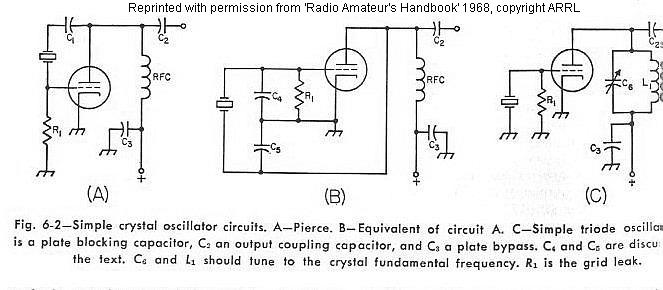
The frequency of a crystal-controlled oscillator is maintained with high precision through the use of a quartz crystal. The frequency is primarily determined by the dimensions of the crystal, particularly its thickness, while other circuit parameters have minimal impact....

Transistors Q1, Q2, and Q3 monitor the two outputs of the stereo amplifier. If the offsets exceed 2 V, Q7 is turned off, which in turn deactivates Q8 and the normally on relay. Diodes D2 and D5, along with...
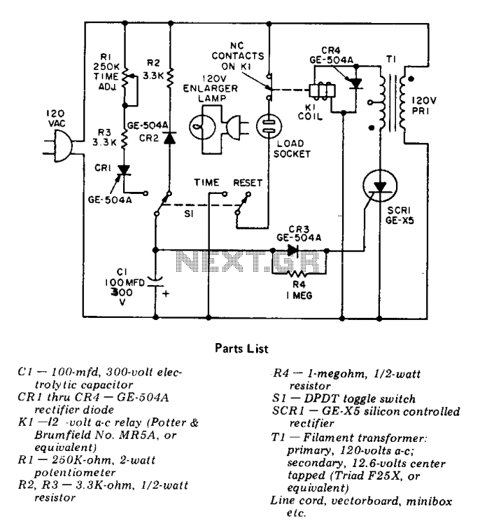
This precision solid-state time delay circuit features both delayed off and delayed on switch functions, which can be interchanged by simply swapping the relay contacts. The described time delay circuit is designed to provide precise control over the timing of...
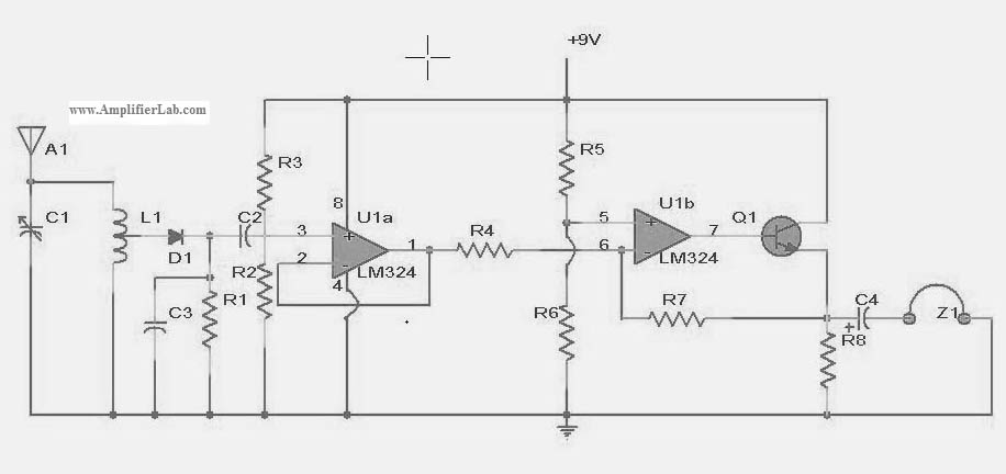
The following circuit illustrates a power amplifier electronic circuit, specifically a tube audio RF amplifier circuit diagram. This circuit is based on the LM324 integrated circuit. The power amplifier circuit utilizing the LM324 operational amplifier is designed to enhance audio...

This fast circuit is compatible with any amplifier that has a line or high-level input (radio, CD) that allows mixing signals from a microphone with a chosen music source and adding adjustable sound effects to the voice. The circuit...
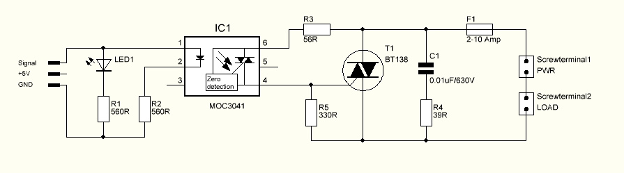
The triac is expected to activate and illuminate the light at nearly 100% brightness; however, it does not turn on at all. If the gate is continuously triggered (i.e., a constant voltage is applied to the gate), the light...