
pc based digital ic tester

The described circuit involves several key components, namely various logic gate integrated circuits (ICs) and a microcontroller. The ICs listed include the 7400 (quad 2-input NAND gate), 7402 (quad 2-input NOR gate), 7404 (hex inverter), 7408 (quad 2-input AND gate), 7432 (quad 2-input OR gate), and 7486 (quad 2-input XOR gate). Each of these ICs performs specific logical operations essential for digital circuit design.
The microcontroller AT89S52, which is part of the Atmel 8051 family, is programmed to interface with a PC via a serial or USB connection. The Visual Basic program running on the PC serves as a user interface, allowing the user to input the specific IC number they wish to test. Upon receiving this input, the microcontroller accesses the corresponding truth table for the selected logic gate, which defines the expected output for all possible input combinations.
The microcontroller then simulates the logic function of the selected IC by applying the relevant inputs and comparing the output against the expected results outlined in the truth table. After the evaluation, the microcontroller sends the results back to the PC, where the Visual Basic program displays whether the tested IC behaves as expected or if there are discrepancies.
This process not only aids in validating the functionality of the ICs but also serves as an educational tool for understanding digital logic design and the operation of various logic gates. The integration of software and hardware in this manner exemplifies the practical application of microcontrollers in electronic testing and verification systems.Check the following IC`s7400, 7402, 7404, 7408, 7432, 7486. Visual Basic Program is used to show the results on the PC. The Microcontroller AT89S52 receives the IC number from the PC and check the Gates IC with the Truth table and sent back the result to the PC. 🔗 External reference
Related Circuits
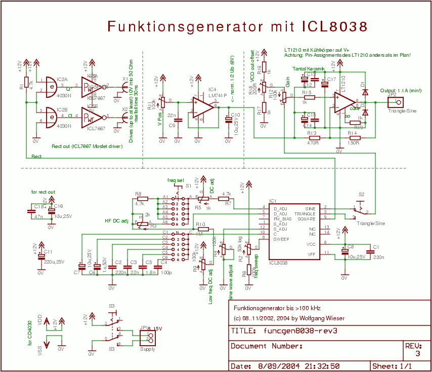
The circuit design is relatively straightforward. It features a Voltage Controlled Oscillator (VCO) utilizing the ICL8038 along with supplementary components, a sine and triangle output stage using the LT1210, and a CMOS-compatible output stage driven by the MOSFET driver...
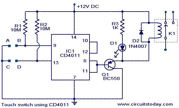
The following circuit illustrates a Touch Switch Circuit Diagram. This circuit is based on the CD4011 IC. Features include R1 and R2, which are the logic gates of the circuit. The Touch Switch Circuit utilizes the CD4011 integrated circuit, which...
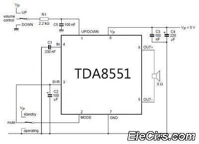
An amplifier with digital volume control can be designed predictably due to the simplicity of the circuit, which utilizes a single chip, the TDA8551. This series of mini amplifiers with digital volume control operates as a BTL (Bridge-Tied Load)...
The RF Tester (A3014) is a combination of four circuits designed to test various circuit concepts by implementing them and providing enhanced support circuits for their development. The Modulating Transmitter (A3014MT) replaces the previous Modulating Transmitter (A3001A) and allows...
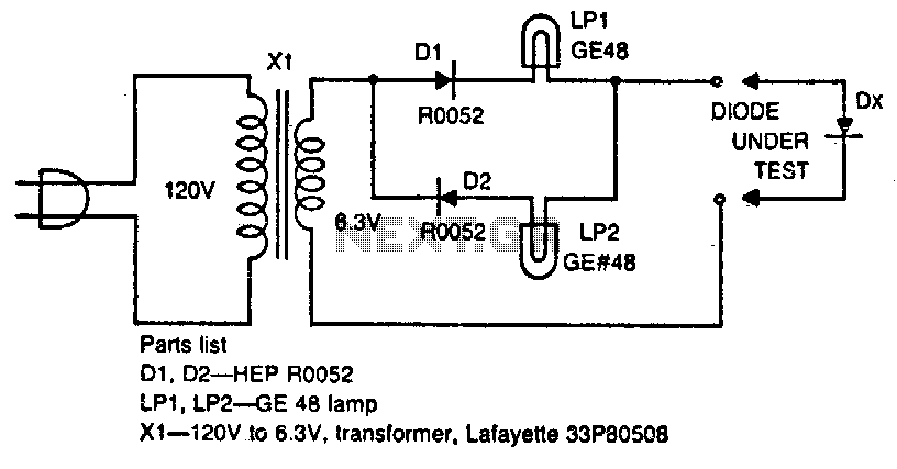
The circuit tests whether a diode is open, shorted, or functioning correctly. If lamp A lights, the diode under test is functional. When lamp B is lit, the diode is good but connected backwards. When both lamps are lit,...
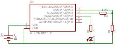
When first discovering this article, it was noted that it is a great project utilizing only a few components. Microcontroller projects based on LEDs are of particular interest. This project is very simple and worth trying. It is inspired...