
PC FM Radio circuit

The FM radio receiver circuit is designed to facilitate the reception of FM signals, allowing users to listen to radio broadcasts through a personal computer. The circuit typically consists of several key components, including an antenna, a radio frequency amplifier, a demodulator, and audio output stages.
The antenna captures the FM signals, which are then amplified by the radio frequency amplifier to ensure a strong enough signal for processing. The demodulator extracts the audio information from the modulated carrier wave, converting it into an audio signal. This audio signal is subsequently passed to the audio output stage, where it can be further amplified and sent to speakers or headphones.
The inclusion of potentiometers P1 and P2 provides user control over the audio output and frequency tuning, respectively. P1 allows for the adjustment of sound intensity, enabling the listener to set a comfortable volume level. P2 permits fine-tuning of the reception frequency, allowing users to lock onto their desired radio station more accurately.
For those interested in integrating this circuit with a PC for frequency monitoring, additional components may be required, such as a microcontroller or an analog-to-digital converter (ADC). These components can facilitate the digital representation of the received signal, enabling real-time frequency analysis and visualization on the computer.
This FM radio receiver circuit is versatile and can be adapted for various applications, including educational projects, hobbyist experiments, or as a foundational element in more complex audio systems. Proper assembly and tuning of the circuit will yield optimal performance, allowing users to enjoy high-quality FM radio reception.This is a fm radio receiver circuit which can be used with PC.PC radio REGULATIONSA) With the P1 we regulate the intensity of sound.B) With the P2 we regulate the frequency of reception.C) Optionally: If you want to check the frequency with your PC it will be supposed you make the following energies:- You assemble and the circuit that is in the blue frame.-.. 🔗 External reference
Related Circuits
A clock-and-data recovery (CDR) circuit is utilized to recover the clock from a transmitted data stream and re-time that data with the recovered clock. These circuits are generally positioned at the front-end of receiver chips to extract the clock...
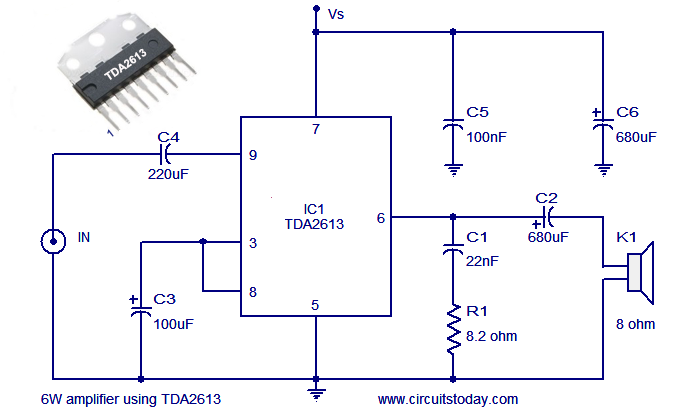
A simple and easy-to-build Hi-Fi audio power amplifier circuit is presented here. This 6-watt Hi-Fi audio amplifier circuit utilizes the TDA2613 integrated circuit (IC). The circuit design employs the TDA2613, which is a high-performance audio amplifier IC known for its efficiency...
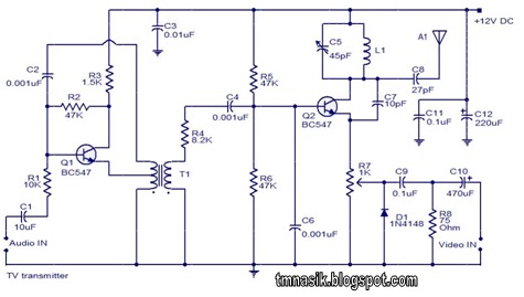
The TV transmitter circuit described utilizes UK standard 1 FM modulation for audio and PAL modulation for video. The audio signal intended for modulation is first amplified using transistor Q1 and its associated components. Transistor Q2 serves dual purposes:...
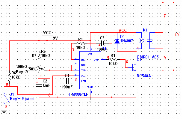
The 555 Timer has extensive applications in electronics. This document describes the use of the 555 Timer in a monostable multivibrator configuration to trigger a transistor driver that energizes a relay, which in turn operates a 230V AC lamp...
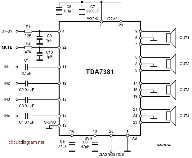
The amplifier is a quad amplifier circuit (amplifier with four inputs and four outputs) based on the TDA7381. This amplifier is designed for car audio systems, but it can also be utilized for other applications. The circuit has a...
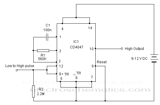
The CD 4047 is a low-power monostable and astable multivibrator that requires only an external capacitor and a resistor to produce output pulses. The CD 4047 integrated circuit (IC) is designed for generating precise timing pulses and can operate...