
PC parallel port Null Printer Adapter

The described circuit functions as an adapter that simulates a printer connected to a PC's parallel port. This is particularly useful for developers who wish to test various printing software or incorporate parallel port communication into their designs without the complexities of direct hardware control. The adapter is constructed using a minimal number of wires, which simplifies the design and implementation process.
To ensure proper functionality, the circuit manages several signals from the parallel port. The Busy and Paper Out signals, which indicate the printer's state, are pulled low by connecting them to ground. This action informs the computer that the printer is ready to receive data. Conversely, the Select and Error signals are maintained high, linking them to the reset output of the parallel port. This configuration allows the computer to recognize the adapter as an active device.
The Acknowledge signal, which is crucial for data transmission, is driven directly from the Strobe line. This arrangement allows the adapter to respond appropriately to data being sent from the computer, facilitating communication without the need for generating handshaking signals within the user's circuit. However, it is important to note that while the adapter allows for the use of standard operating system printing functions, it does not inherently support the necessary handshakes, which may limit its compatibility with certain applications or software that rely on these signals for proper operation.
Overall, this simple yet effective circuit serves as a bridge for connecting various circuits to a parallel port, enabling easier communication and testing while circumventing some of the limitations imposed by operating systems on direct hardware access.This circuit is a simple adapter for PC parallel port to think that there is a printer connected to computer. This adapter is useful for testing printing speed with different software and as a part of your own designs.
You can use this circuit to connect your simple circuits to the parallel port. Usually many home-made circuits use parallel port in a way which you have to use direct I/O commands to control the parallel port to be able to communicate to your circuit. Unfortunately this approach is not always possible, because some operating system prohibit the programs to directly control the computer hardware.
With this adapter you don't have to worry about generating handshaking signals in your own circuits. This simple circuit consists of only few wires connected to parallel port connector and it makes the computer to think that there is a real printer connected to parallel port and accepting the data. This circuit works using following principles: Bysy and paper out signals which normally come from printer have to be kept low, so they are tied to ground.
Select and error signals which normally come from printer must be kept high, so they are connected to reset output in parallel port. Acknowledge signal is directly driven from strobe line. In this situation you might want to use standard operating system printer printing functions for sending data to your circuit, but it does not work because your circuit does not generate the handshakes that are needed.
🔗 External reference
Related Circuits
This receiver is designed around the widely used ZN414 integrated circuit (IC) and operates within the AM band, covering frequencies from 550 to 1600 KHz. To utilize the receiver for Longwave frequencies, it is necessary to replace the coil...
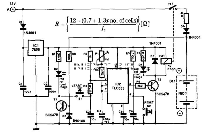
The portable charger is designed primarily for model enthusiasts to charge their NiCad batteries using a car battery outdoors. The circuit's supply voltage is regulated by IC1. When connected to the car battery, LED D2 illuminates only if the...
The Lazy Adapter is composed of a 20 pin DIP socket, a 20 pin DIP header, and a 6 pin ISP header, and a small phenolic circuit board to hold them all together. The green fiberglass PCB is a...
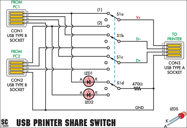
This simple device enables two computers to share a single USB printer or other USB devices, such as an external flash drive, memory card reader, or scanner. A rotary switch is used to select the PC that will be connected...
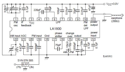
This portable AM/FM radio circuit is designed using the LA1800 integrated circuit (IC) along with several external components. The LA1800, manufactured by Sanyo Semiconductors, requires only a few additional components for its operation. The output signal is directed to...
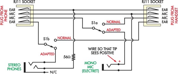
Here is a more affordable and simpler method to create a telephone headset adapter. The only components needed are an inexpensive headset (available for $5 at Harvey Norman), a DPDT switch, and... To construct a telephone headset adapter using the...