
pcb Driving 10x10 LED matrix with AVR

The project involves creating a printed circuit board (PCB) to control a 10x10 LED matrix clock. The core of the design is based on the ATmega328 microcontroller, which is a popular choice for embedded applications due to its versatility and ease of programming. The Maxim DS3234 is utilized as a real-time clock (RTC), facilitating accurate timekeeping.
To manage the 10x10 LED matrix, which consists of 100 individual white LEDs, a suitable driving mechanism must be implemented. The initial plan to use the MAX7219 or MAX7221 integrated circuits is not feasible, as these components are designed to handle only 8x8 matrices. Therefore, alternative approaches must be considered to effectively control the larger matrix.
One potential solution is charlieplexing, a technique that allows for the control of multiple LEDs using fewer pins by exploiting the tri-state logic of microcontroller I/O pins. This method is particularly advantageous for large matrices but requires careful planning of the circuit layout and programming logic to ensure that the correct LEDs are illuminated without unintended activations.
The ULN2803 darlington transistor array can be employed to handle the higher current requirements of the white LEDs, which necessitate at least 30mA for optimal brightness. The ULN2803 consists of eight darlington pairs, allowing it to control multiple LED rows or columns efficiently. Each output of the ULN2803 can sink significant current, making it suitable for driving the LEDs directly from the microcontroller.
In summary, the design of the controller PCB for the 10x10 LED matrix clock requires a combination of the ATmega328 microcontroller and the DS3234 RTC, along with a charlieplexing scheme and the ULN2803 transistor array to achieve the desired functionality and brightness of the LEDs. Careful consideration of the circuit design, including the arrangement of the LEDs and the programming of the microcontroller, will be essential to ensure reliable operation and performance of the clock display.Designing a controller PCB for a 10x10 white LED matrix clock (inspired by the tutorial here ). It`s based off an ATmega328 AVR IC and Maxim DS3234 SPI RTC. However, I`m stuck: I have no idea how to control my custom non-standard 10x10 LED matrix. Originally I was going to use a Maxim MAX7219/7221 IC, but it can only drive 8x8 LED matrices. Then I was looking at some sort of charlieplexing solution with a ULN2803 darlington transistor array. The bright white LEDs I`m using need at least 30mA of current. 🔗 External reference
Related Circuits
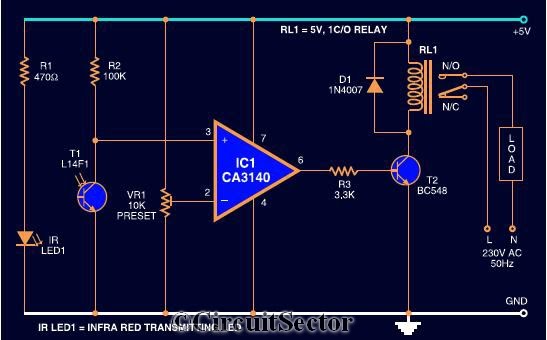
The circuit diagram presented is a highly sensitive wireless relay switch designed to control home appliances such as flush systems and hand dryers. This wireless switch operates without the need for a remote control. It functions by simply moving...
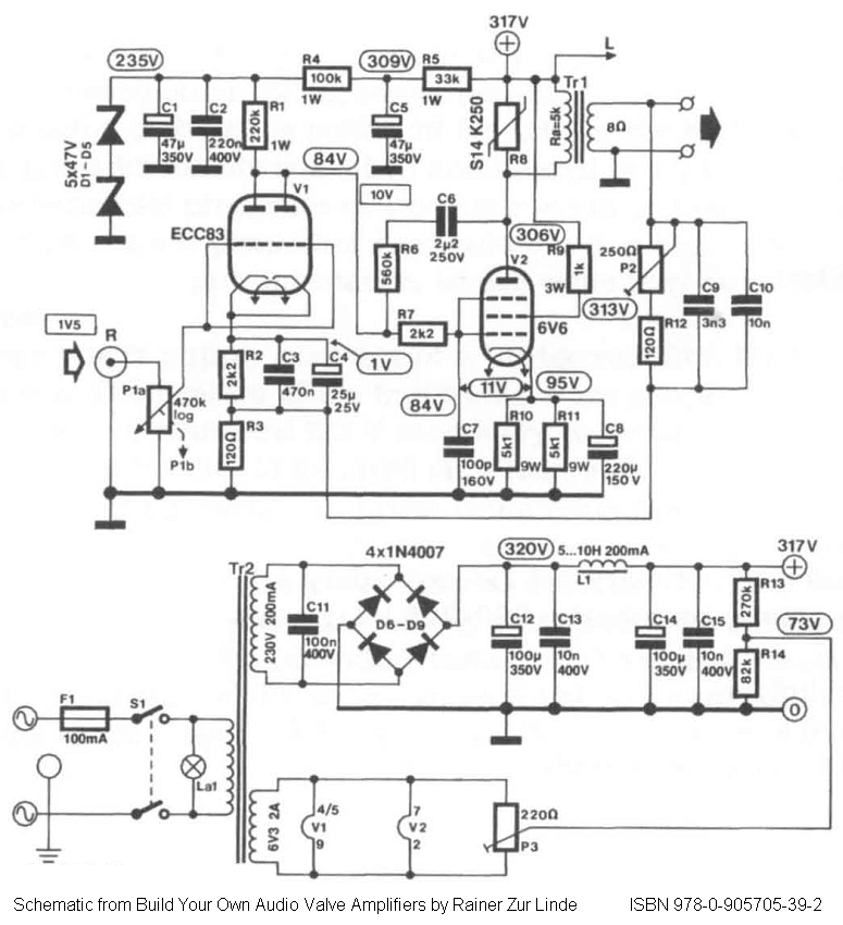
Direct-coupled single-ended (SE) 6V6 and 6V6GT tube amplifier schematic with ECC83 driver stage. From the book "Build Your Own Audio Valve Amplifier" by Rainer zur Linde. The described circuit represents a direct-coupled single-ended tube amplifier utilizing 6V6 or 6V6GT vacuum...
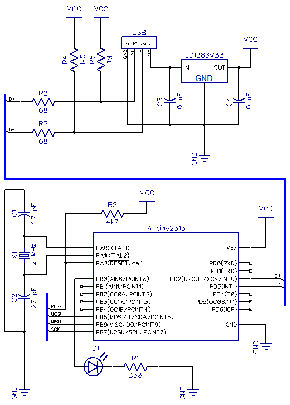
This is the second part of a USB tutorial for the ATtiny2313 microcontroller and the V-USB library. The first part covered how to derive 3.3V from USB to power circuits. In this section, the setup will be expanded with...
Martin Ustek has modified the project to include a Sokoban game. Information about his version can be found throughout this page; for full details, please visit his website (Czech). Either game can be selected with a menu that appears...

The SP6331, SP6333, and SP6335 are quad power supervisory circuits designed for microprocessor reset applications, featuring multiple reset voltage options. This family of devices offers low voltage monitoring capabilities for up to four supply voltages, with two precision factory-set...
This circuit was designed as a warning flasher to alert road users to dangerous situations in the dark. Alternatively, it can act as a bicycle light. The circuit operates by utilizing a light-emitting diode (LED) as the primary visual alerting...