
Peak Reading Audio Level Meter

The circuit operates by first amplifying the audio signal using a non-inverting operational amplifier configuration. The operational amplifier is chosen for its high input impedance, which allows it to interface effectively with various audio sources without loading them down. The inclusion of the 1N4148 diode in the feedback path is critical, as it allows only the positive half-cycles of the audio signal to pass through, effectively rectifying the waveform.
The output of the operational amplifier is then connected to the smoothing capacitor (22 µF), which serves to filter out the high-frequency components of the rectified signal. As the audio signal peaks, the capacitor charges up to the peak voltage level. The discharge path, which includes the analog meter and an 18 kΩ resistor, determines how quickly the meter responds to changes in the audio signal. The resistor value, in conjunction with the capacitor, sets the time constant for the discharge, allowing the meter to indicate the peak level for a brief period before it begins to fall back.
This design is adaptable; different capacitors can be used to modify the response time of the meter. A larger capacitor will prolong the discharge time, making it suitable for applications where sustained peak readings are necessary. Conversely, omitting the capacitor enables the circuit to act as a true peak level indicator, reflecting instantaneous audio levels. The circuit's simplicity and effectiveness make it an excellent choice for audio level monitoring in various applications, including recording studios and live sound environments.Using minimum component count; this simple circuit will indicate peak audio response on an analogue meter, similar to a tape recorders meter. The circuit uses an op amp as a non inverting amplifier, but with one addition - a diode in the feedback loop.
The circuit has a fast response time and slow decay time to indicate peak readings. The 1N4148 d iode provides half wave rectification of the input signal, the dc output being smoothed by the 22u capacitor. the capacitor will charge to the peak value of the input waveform, and then discharge via the meter and 18k resistor.
I used a meter with a FSD of 150uA, but any meter with a FSD in the range 50-250uA may be used. The discharge time is around a quarter of a second. Increase the 22uF cap for a longer discharge time, or omit altogether to make an instantaneous reading level meter. 🔗 External reference
Related Circuits
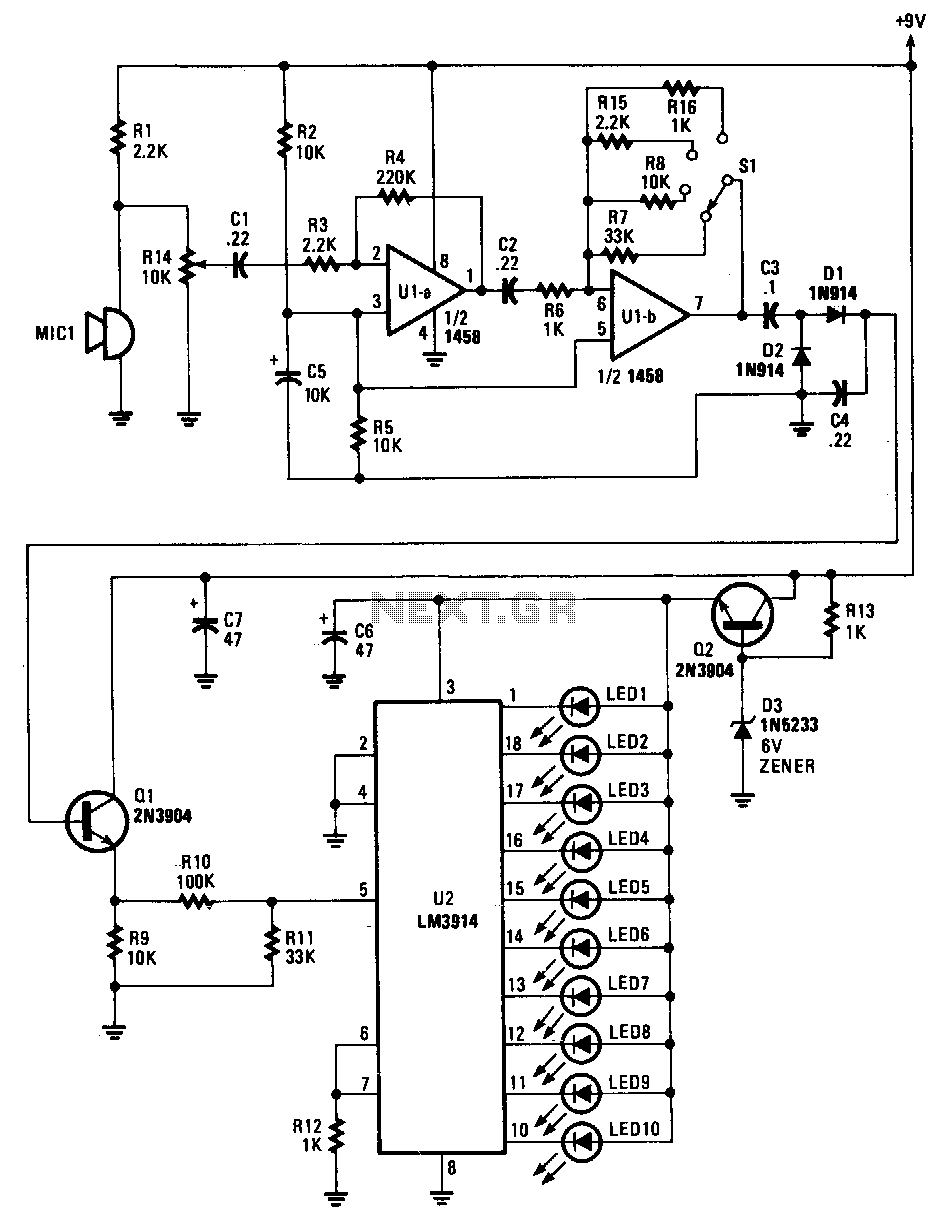
Sounds are captured by MIC1 and sent to the input of the first operational amplifier (op-amp). The signal is subsequently directed to the input of the second op-amp, U1B, where it is amplified by a factor ranging from 1...
This is a signal injector designed for individuals who may not have access to extensive test equipment. It can be utilized for tracing audio circuits during troubleshooting or for testing audio circuits that require an input signal. The injector...

The Dutch magazine Audio & Techniek once published an article about one-way loudspeakers that were based on Audax units. Although speakers using just a single full-range unit per audio channel were disregarded in audiophile circles due to high intermodulation...
Incorporate resistors in a parallel configuration to enhance audio input. To control the volume for each input channel, integrate a linear trimmer or potentiometer with the following configuration: pin 1 connects to ground, pin 2 serves as the output,...
This Hartley oscillator was constructed using a single 45 tube and is based on a design published in a 1932 QST article by George Grammer. The initial circuit experienced performance issues due to weak 45 tubes, necessitating a very...

Ensure that the 12V (yellow) wire is connected to the right side of the D-connector (viewed from behind, with the connector holes facing away and the curved portion of the connector oriented upwards). The D-connector, commonly utilized in various electronic...