
Permanent Magnet Motor Control with SCR

The Permanent Magnet Motor Control circuit is designed to efficiently manage the performance of permanent magnet motors, which are widely used in various applications due to their high efficiency and compact size. The schematic typically includes key components such as a microcontroller, power transistors, and feedback mechanisms to regulate motor speed and torque.
At the core of the circuit is the microcontroller, which processes input signals from sensors or user interfaces to determine the desired motor performance. The microcontroller sends control signals to power transistors or MOSFETs, which act as electronic switches to regulate the voltage and current supplied to the motor. This allows for precise control over the motor's speed and direction.
Feedback mechanisms, such as encoders or Hall effect sensors, are often integrated into the circuit to monitor the motor's actual speed and position. This data is fed back to the microcontroller, enabling closed-loop control that adjusts the input signals based on real-time performance, ensuring optimal operation and preventing issues such as stalling or overheating.
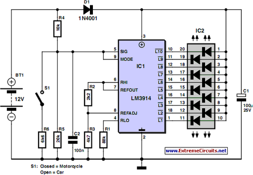
Additional components may include capacitors for filtering, diodes for protection against back EMF, and resistors for current limiting. The layout of the circuit is crucial for minimizing electromagnetic interference and ensuring stable operation. Proper grounding and component placement are essential to enhance the overall reliability and performance of the Permanent Magnet Motor Control circuit.This is a schematic diagram of Permanent Magnet Motor Control circuit. This circuit is used to control the permanent magnet control. This circuit uses. 🔗 External reference
Related Circuits
This is a TV remote control jammer circuit. Remote controls use modulated light to combat interference from background infrared noise. Your room heater, etc. The TV remote control jammer circuit is designed to disrupt the operation of infrared remote controls...
Camping today often requires carrying various electronic devices for daily activities and entertainment. Typically, a charged lead-acid battery and a power inverter are utilized to ensure a well-organized trip, allowing family members to use their electronic devices comfortably. It...
An EEPROM is a type of non-volatile memory, which means it is used for permanently storing digital data without any power supply. EEPROM stands for Electrically Erasable Programmable Read-Only Memory. The advantage of this type of ROM is that...
Wiper Speed Control. A continuously operating wiper in a vehicle can be bothersome, particularly during light rain. The circuit described here allows for the adjustment of the wiper's sweeping rate, ranging from once per second to once every ten...
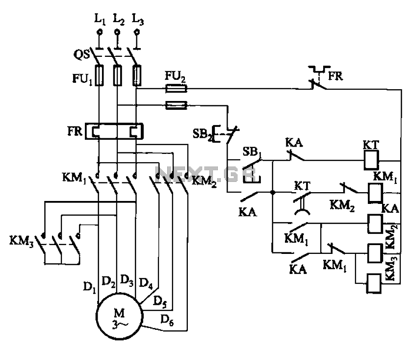
The circuit depicted in Figure 3-99 illustrates a low start-up mechanism for a motor, which transitions to high-speed operation automatically. The start-up process is facilitated by a shaped connection, while the transition to high-speed operation is managed by a...
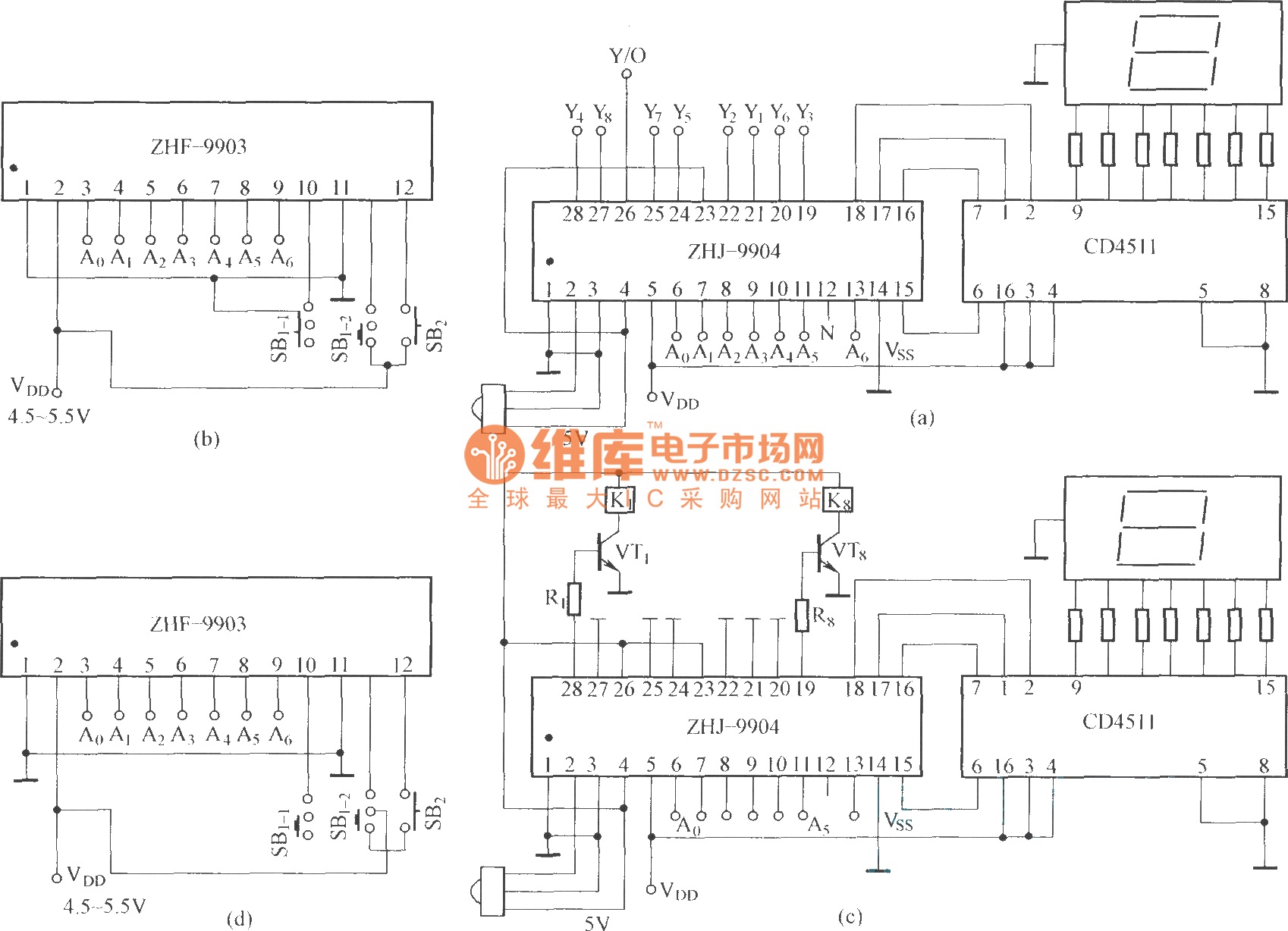
This is an eight-way signal remote control selection circuit composed of ZHJ-9904. It includes a remote control transmitter circuit, an eight-way switch control circuit, and a remote control transmitter. The eight-way signal remote control selection circuit utilizing the ZHJ-9904 is...