
Wiper Speed Control

The wiper speed control circuit typically employs a variable resistor or potentiometer to adjust the timing of the wiper motor operation. This circuit can be implemented using a simple timer IC, such as the NE555, configured in astable mode, to generate a square wave output that drives the wiper motor.
The key components of the circuit include the NE555 timer, a motor driver (such as a transistor or a relay), a potentiometer for speed adjustment, and capacitors for timing control. The potentiometer alters the resistance in the timing circuit, thereby changing the duty cycle of the output signal. This adjustment directly influences how often the wipers sweep across the windshield.
In the astable configuration, the NE555 timer continuously oscillates between its high and low states, which can be set to correspond to the desired wiper speed. The output from the NE555 can be fed into a transistor, which acts as a switch to control the wiper motor. The motor will then operate at the speed determined by the timing circuit, allowing the driver to set a comfortable wiper frequency based on the current weather conditions.
Additionally, diodes can be incorporated to protect the circuit from back EMF generated by the motor, ensuring the longevity and reliability of the wiper speed control system. This setup enhances the driving experience by providing customizable wiper functionality, adapting to varying levels of precipitation.Wiper Speed Control. A continuously working wiper in a car may prove to be a nuisance, especially when it is not raining heavily. By using the circuit described here one can vary sweeping rate of the wiper from once a second to once in ten seconds
🔗 External reference
Related Circuits
This circuit is a stable frequency counter with an accuracy of 5 significant digits. It operates within a frequency range of 0 to 30 MHz and has an input sensitivity greater than 100 mV. The probe connects to the...
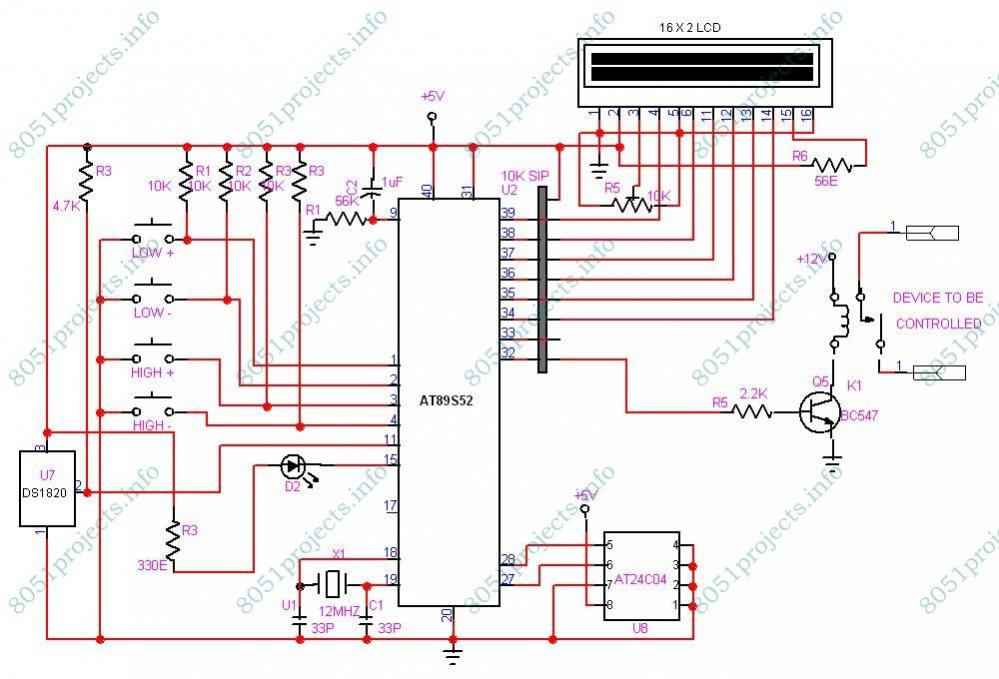
This project is designed to monitor and control temperature. The system utilizes the DS1820 temperature sensor to measure the temperature, which is then displayed on an LCD. It features two preset levels: a low preset and a high preset....
In certain locations near the reservoir or well, when the water level is constrained by the water towers, there is a need for simultaneous monitoring of the water towers and reservoirs as part of an automatic water control system....
The circuit presented utilizes a two-transistor "flasher" to generate triggering pulses, replacing the traditional unijunction transistor design. This configuration allows for a broad range of control with minimal hysteresis and sensitivity to line voltage. Two diodes rectify the line...
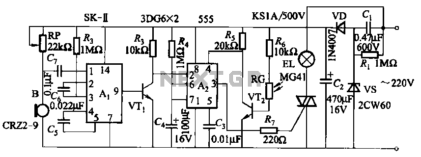
This circuit utilizes a dedicated voice integrated circuit (AI) of the SK type, which incorporates an internal bistable multivibrator and three inverting amplifiers. The 555 integrated circuit (IC) A2 is employed for delay control. The described circuit is designed to...
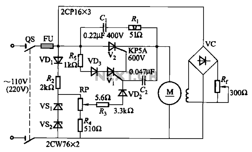
A 100W resistance-triggered motor control circuit designed for arc welding machines. It features an adjustment potentiometer (Rr) that can modify the DC motor excitation current. Additionally, a regulator (RP) is included to adjust the DC motor armature voltage, enabling...