
Air conditioner microcomputer control circuit

The circuit includes protective components (IC2, VD1, and G) that safeguard the electrical system. When the compressor operates, P5 is high, allowing voltage to pass through IC2 and VD1, charging the resistor G. If the compressor stops, P3.5 goes low, and P2.5 remains high for a period of approximately 3 minutes to prevent immediate restart, thereby protecting against power surges and operational errors that could lead to compressor damage due to environmental temperature fluctuations.
The microcontroller continuously monitors the power supply voltage. If the voltage falls below 190V or exceeds 270V, the air conditioner ceases operation and displays an error message (E01). Normal operation resumes when voltage levels are restored. The system also includes a frost detection feature: if a refrigerant leak or blockage occurs, the lower section of the evaporator may frost excessively. When the frost thickness reaches 2mm, the thermistor (RT2) detects the low temperature, prompting the microcontroller to halt operation and display an error message (E02) for maintenance.
The wind speed can be adjusted using button SB1. Continuous pressing of SB1 sequentially activates the fan at low, medium, and high speeds. Buttons SB2 and SB3 are used for temperature setting, allowing the user to adjust the setpoint by increasing (SB2) or decreasing (SB3) the temperature in 1°C increments, with a settable range of 15°C to 30°C. The system can be stopped using button SB4, which saves the current temperature, setpoint, and fan operation data in IC9 before halting all operations.
The schematic for this temperature control circuit should include the AT89C52 microcontroller, connections for the thermistors, the compressor relay, voltage monitoring circuitry, and the various push buttons for user control. Each component should be clearly labeled, with appropriate connections indicated to ensure easy understanding and troubleshooting of the circuit. The power supply section must also be highlighted to show the voltage monitoring and protection features effectively. Circuit works as follows: Computer logo conditioned clamor control circuit shown in Figure 1-58, the main chip AT89C52 microcontroller with Levin. Switched power source when, 2 4C02 microcontroller first reads from the last saved setpoint temperature extravagant irresolute Rang Winds running state data, then shame relaxation in standby mode. Press a ON/OFF button SB.. Lan began to run empty, the fan-shaped Zhu noted last dice Organisation of operation J thermistor RTl detect indoor temperature, the conversion process after ryD displayed on the digital value of the current actual temperature stag} beans illustrating the range of -20- - + 40C, when the temperature is below the set value when, P3.5 output low, the compressor is not running, when the temperature is higher than the set value and P2.5 pin is low, P3.5 output high level, K4 ai station, compressor work.
ICZ, VD1, G, compression set sail constitute protected electrical gizzard, when the compressor is working, since P.5 is high level, the voltage through IC2, VD1 resistant G charged and the P2.5 is high, when the compression when the machine stops, P3,5 is low, then cl of product discharge, P2.5 period of time (about 3min) still remains high almost, in this process, the compressor will not start again, so avoided by the instantaneous power, protection, and the use of improper operation and other temperature fluctuations in the environment cause the compressor frequent start and harm. During operation, the microcontroller is also constantly monitored by RP1 power supply voltage level.
If less than 190V or higher than 270V, stop air conditioner is working o germanium and displays error message E01, continue to work when the voltage is normal. I installed in the boat where a transcript of the lower portion of the orbital evaporator evaporator 2tn/0!
And glass when a refrigerant leak, blockage failure. The lower part of the evaporator will be more severe frost, when the thickness of the frost cool to 2 mtn., When tRT2 exposure to frost and thus feel a lower temperature, the microcontroller detects this information, cause the air conditioner stops working and displays an error message E02 stretch, prompting the user for maintenance .SBlr wind speed Setup button and in the operation of the continuous press SB1, Ki, K2, K3 in turn closes respectively connected fan of low, medium, high-speed winding, according to the fan corresponding speeds .SBZ and SB3 temperature setting key, press the SB2 is running or SB3, digital display of temperature change to the display by the temperature setting value, then press under S touch. G given temperature increase of 1, click SB3, reduce. 1, set the range 1S ~ 30 : the stop button lOs after - and converted into digital display the current temperature values need to shut down when deer; click SB4 microcontroller to the current temperature.
setpoint and fan operation data stored IC9 save, and then stops.
Related Circuits

This is a design of the circuit diagram for an RS422 interface. Connector K1 is connected to the serial port of the PC, and power for the PC side of the circuit is obtained from the signal lines DTR...
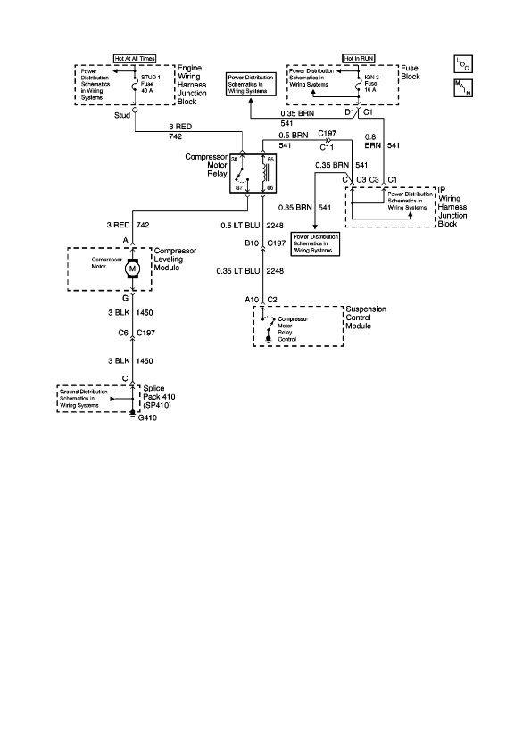
The physical location of the compressor relay is needed, as well as instructions on how to test the pressure sensor on the plastic tank of the compressor assembly. The exact location of the relay has not been confirmed, but...
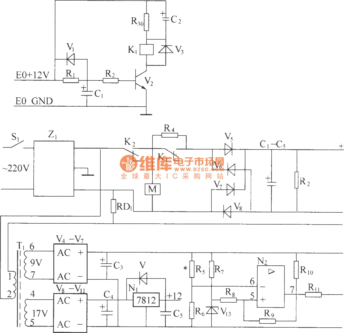
220V (5Hz) alternating voltage passes through the Z1 circuit filter, which filters the signal before sending it to the connection point of the AC over-voltage and under-voltage protection relay K2. During normal operation, the K2 connection point should be...
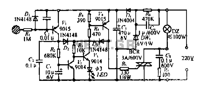
Diagram 2 depicts a shake tube circuit with a capacitance (C) and a trigger voltage rectifier filter element. The circuit includes a trigger voltage transistor amplifier (H), three pull tubes (n, U, v), and utilizes a thyristor as a...
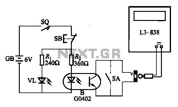
An electronic calculator features an automatic counting interface circuit, as illustrated in the accompanying figures. Figure (a) depicts a stroke switch controlled via optocoupler B. Figure (b) shows the application of a reed switch (KR) for pulse control signals....
A schematic arrangement for a two-quadrant controller is shown in the figure below. This figure illustrates the outer speed control loop and the inner current control loop. The tachogenerator derives the speed feedback signal; alternatively, an approximation of the...