
Phase sequence indicator
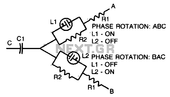
The phase-sequence indicator operates by utilizing the characteristics of neon lamps, which only light up when the voltage across them exceeds a certain threshold. In a polyphase system, the voltage levels across the different phases can vary due to load imbalances or phase shifts. The two neon lamps in this circuit are connected in such a way that one will illuminate when the voltage on one phase is higher than the other, thus indicating the phase rotation.
The resistors in the circuit serve to limit the current flowing through the neon lamps, ensuring that they operate within their specified limits and preventing damage. The capacitor is used to stabilize the circuit by filtering out any high-frequency noise that may interfere with the reliable operation of the indicator.
Typical component values for the resistors and capacitor may vary depending on the frequency of the circuit being tested, as indicated in the accompanying table. For example, at lower frequencies, larger resistor values may be required to ensure proper operation, while at higher frequencies, smaller values may suffice. The selection of these components is critical to ensure accurate phase detection and to maintain the longevity of the device.
The overall design of the phase-sequence indicator is compact and portable, making it suitable for field applications where quick verification of phase rotation is necessary. This device is particularly useful for electricians and technicians working with three-phase systems, as incorrect phase rotation can lead to equipment damage or operational inefficiencies.Simple, portable phase-sequence indicator determines the proper phase rotation in polyphase circuits. Major components are two neon lamps, two resistors, and a capacitor. In operation, the leg voltages are unbalanced, so that the lamp with the maximum voltage—or proper phase sequence—lights
Table shows typical component values for various circuit frequencies. 🔗 External reference
Related Circuits
The circuit was designed to provide an indication before a 12 V lead-acid battery reaches a discharged state using an LM723 voltage regulator and a positive NPN standard voltage. The circuit utilizes the LM723 voltage regulator, which is well-suited for...
One method of controlling power to AC circuits utilizes a triac to switch the power on and off at precisely timed intervals synchronized with the AC signal. This technique is referred to as AC phase control and is commonly...

Back panel terminal connectors include audio out, trigger in, clock in, clock out, and CV out, along with an internal power supply chord. There is no ON/OFF button; the device operates on a plug-and-play basis. The sequencer features eight...
This circuit controls five outputs at 220V. A potentiometer adjusts the speed, and a switch selects the effect (one direction or both directions). The circuit includes a divider by 10 (4017), a transistor oscillator (2N2646), the power stage, and...
The following circuit illustrates a 2500W Phase Control Circuit Schematic. Features include a ground-tied trigger output that is disabled, and a low voltage input. The 2500W Phase Control Circuit is designed to regulate the power delivered to a load by...
A circuit was constructed based on an LED beating heart frame instructable, but it is not functioning as expected. There is also mention of a built LED sequencer. The LED beating heart circuit typically involves a microcontroller, such as an...