
Phase Shifter With Eight Outputs Circuit

The described circuit employs a configuration of eight identical active phase shifters, arranged in a cascade to achieve precise phase manipulation of input signals. Each phase shifter is controlled by a common DC voltage, allowing for synchronized adjustment across all cells. The tuning of resistor RA is critical, as it calibrates the phase difference to maintain a baseline of zero between the input signals, ensuring that the phase shifts introduced by each cell are uniform and predictable.
The active phase shifters utilize operational amplifiers, which are essential for maintaining signal integrity and providing the necessary gain and phase shift. The output from each operational amplifier corresponds to the phase-shifted signals required for PSK modulation, which is a widely used technique in digital communications. The design ensures that the phase shifts introduced are accurate, with the specification of 1% tolerance for resistors and 5% tolerance for capacitors being crucial for maintaining the circuit's performance and reliability.
Furthermore, the circuit is designed to handle a sine wave input of 1700 Hz, with the amplitude of V1 not exceeding 1 V. This limitation is important to prevent distortion and ensure that the operational amplifiers function within their linear range. The choice of 100-nF capacitors is significant, as their tolerance affects the timing and phase accuracy of the signal processing, thereby influencing the overall performance of the phase shifter circuit.
In summary, this circuit exemplifies a sophisticated approach to phase shifting in electronic communications, leveraging precise component tolerances and operational amplifier technology to achieve reliable PSK signal generation. The circuit consists of eight cascaded identical cells, each ccll being a dc-controlled active phase shifter. Because the dc control is common for all shifters, the circuit is adjusted by trirtuiiing RA so that the phase difference between and Vi is zero.
As a result, each shifter will introduce a phase difference of exactly /r. The eight signals for PSK are available at the op amps` outputs. Phase accuracy is acceptable for 1%-tolerance resistors and 5%-tolerancc 100-nF capacitors. Also, the amplitude of V{ (which is a 1700-Hz sine wave), should not exceed 1 V.
Related Circuits
The power amplifier Hi-Fi OCL 120W RMS is designed to operate effectively when paired with a suitable power supply circuit and 8-ohm speakers. This circuit exclusively utilizes transistors without any integrated circuits, resulting in a clean sound output. The...
The microphone preamplifier circuit design presented in this schematic utilizes the SSM2015 produced by Precision Monolithics Inc. (PMI), which offers high amplification. The SSM2015 is a low-noise, low-distortion integrated circuit designed specifically for microphone preamplification. It features a differential input...
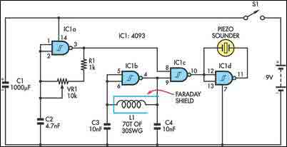
The circuit incorporates two oscillators, both operating at about 40kHz. The first, IC1a, is a standard CMOS oscillator with its frequency adjustable via VR1. The frequency of the second, IC1b, is highly dependent on the inductance of coil L1,...
The video master comprises a series of converters that allocate all video sources to unused UHF channels. These channels are then combined with standard TV channels, whether terrestrial or cable, into a single cable. This single cable can subsequently...
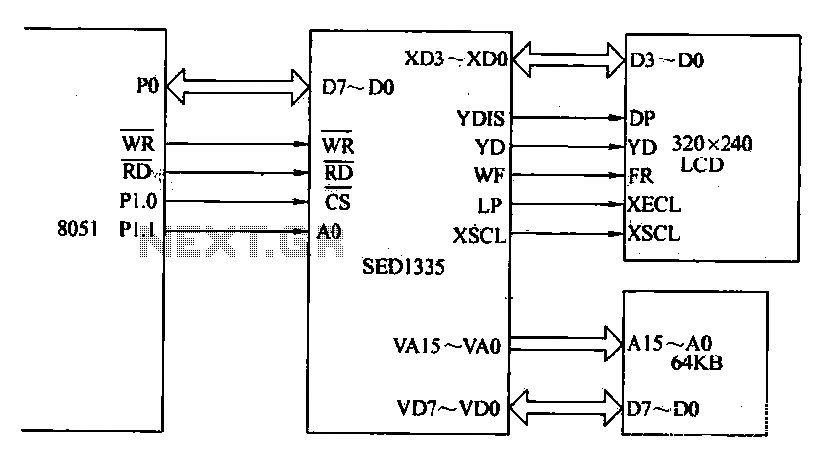
The MCS-51 series single-chip interface circuit 8051 is utilized to control the SED1335 35 dot matrix LCD display. This controller can manage up to a 640x256 dot matrix LCD display for both graphics and character representation, with the capability...
The Electronic Cash Register (ECR) keeps track of sales transactions quickly and effectively. An abundance of PLUs (Price Look Ups) and department keys accommodate a variety of merchandise items. This means a faster, more accurate check out process and...