
Low noise microphone preamplifier circuit
The SSM2015 is a low-noise, low-distortion integrated circuit designed specifically for microphone preamplification. It features a differential input stage that provides excellent common-mode rejection, making it suitable for applications requiring high fidelity audio signal processing. The circuit typically includes resistors and capacitors that set the gain and frequency response to match the characteristics of the microphone being used.
In this schematic, the input stage connects directly to the microphone, converting the low-level audio signal into a more manageable voltage level. The gain of the SSM2015 can be adjusted by changing the feedback resistors, allowing for flexibility in handling different microphone types, such as dynamic, condenser, or electret microphones.
The output stage of the preamplifier is designed to drive subsequent audio processing stages or directly interface with analog-to-digital converters (ADCs). It is important to ensure proper power supply decoupling to minimize noise and maintain signal integrity throughout the circuit. Additionally, the layout of the PCB should be considered to reduce electromagnetic interference (EMI) and ensure optimal performance of the preamplifier.
Overall, the SSM2015 microphone preamplifier circuit is a robust solution for capturing high-quality audio signals, making it a popular choice in professional audio equipment and recording applications.The microphone preamplifier circuit design presented in this schematic use SSM2015 produced by Precision Monolithics Inc. (PMI) which offers a high amplifi. 🔗 External reference
Related Circuits
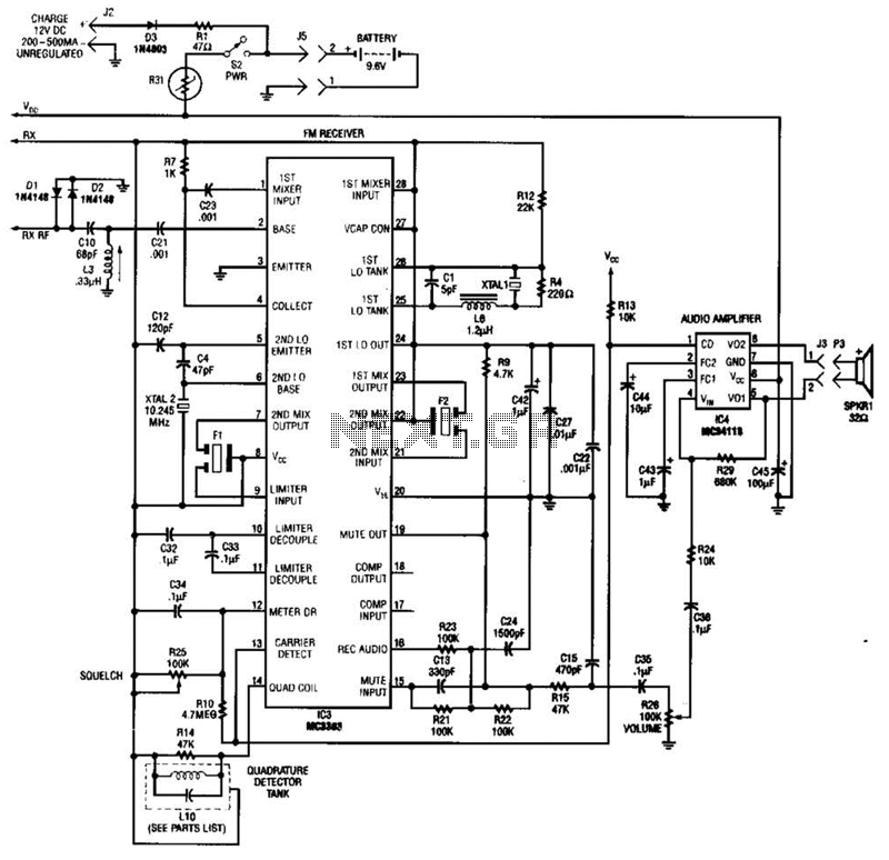
Using a Motorola MC3363 LSI one-chip FM receiver, the circuit is a dual-conversion FM receiver with a 10.7-MHz IF chain. IC4 provides power to drive a small speaker. The described circuit employs the Motorola MC3363 integrated circuit, which is designed...
This analog switch circuit is designed to switch an analog line on or off. It consists of two analog switches in integrated circuit (IC) form that are controlled by two pushbuttons. The described analog switch circuit utilizes two integrated analog...
Ensure that connections are verified against the circuit diagram and schematic provided below. This can be utilized while following the tutorial video. The circuit diagram serves as a crucial reference for accurately assembling electronic components in a project. It illustrates...
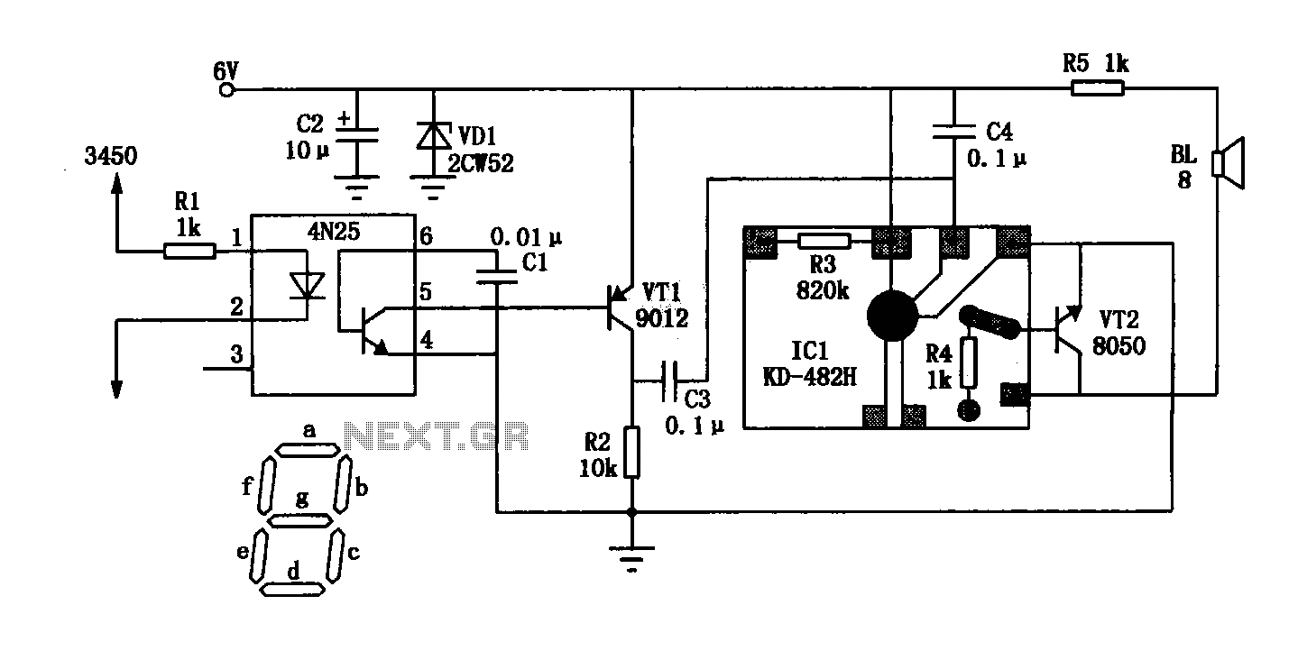
The General Dynamic LED digital clock lacks a timekeeping function, but by adding a simple circuit, it can incorporate this feature. The integrated circuit (IC) includes a programmable mute function, which is inactive from 23:00 to 5:00 to avoid...
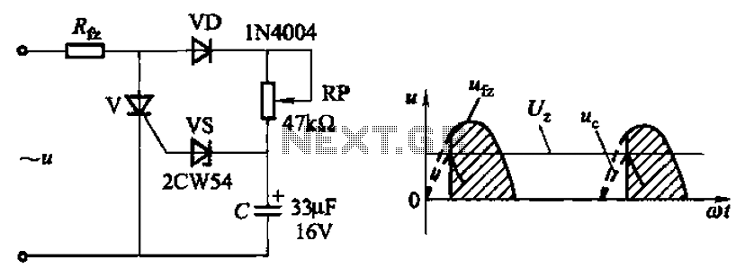
Circuit characteristics: A simple phase shift range of 180 degrees; exhibits good linearity and control accuracy compared to the first two options, making it suitable for low voltage applications, particularly in less demanding electroplating and electrolysis power supplies. The described...
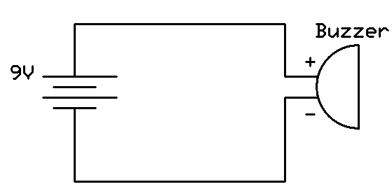
This project involves connecting the positive terminal of the battery to the positive lead of the buzzer and the negative terminal of the battery to the negative lead of the buzzer. Typically, the positive lead of the buzzer is...