
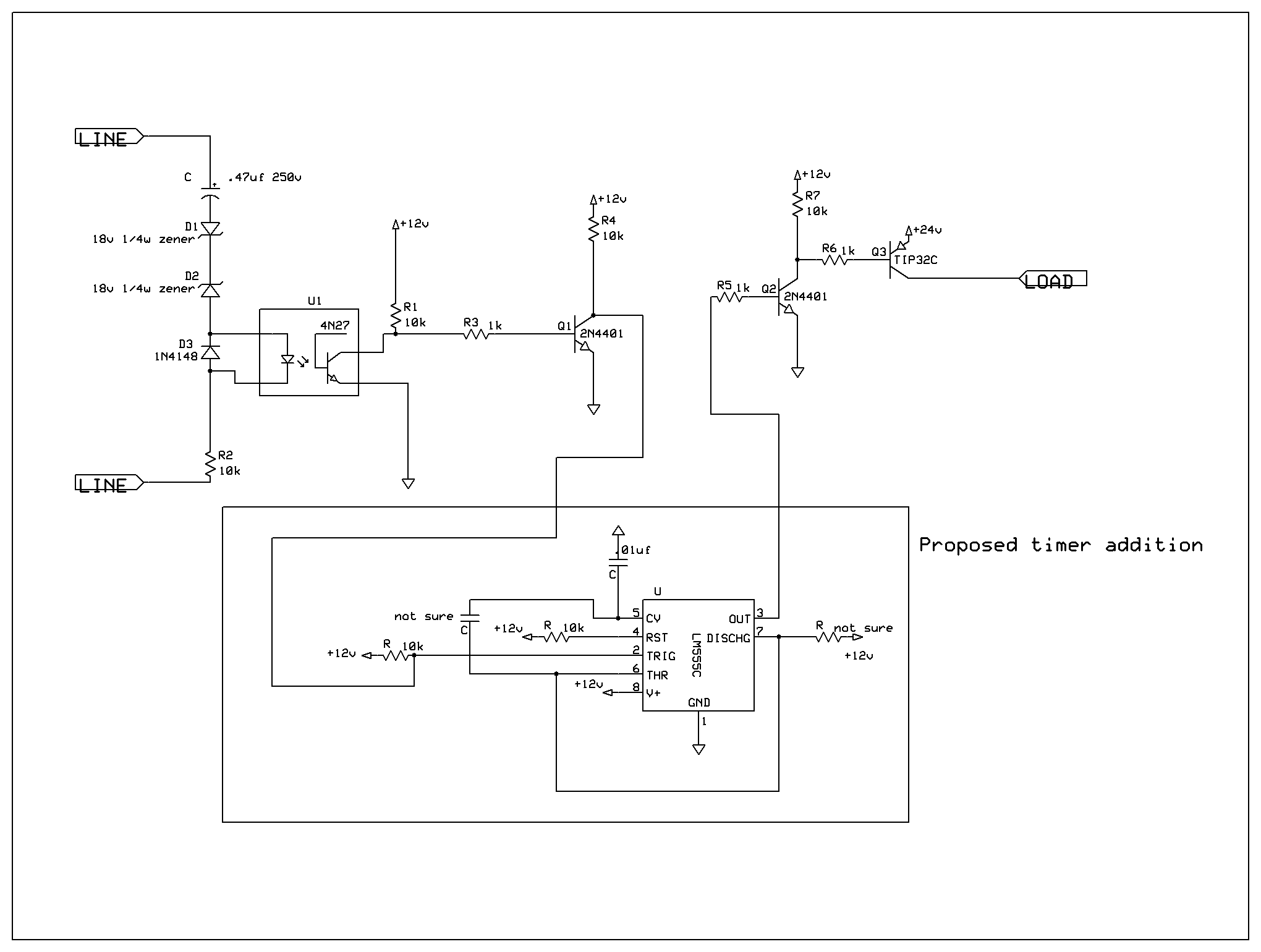
Telephone ringing detector

The circuit utilizes the 555 timer in astable mode to generate a continuous square wave output. This output is then used to control the opto-isolator, which serves as a bridge between the low-voltage control circuit and the high-voltage speaker circuit. The opto-isolator provides electrical isolation, protecting the low-voltage components from high-voltage spikes that may occur in the speaker circuit.
The 555 timer's frequency and duty cycle can be adjusted by varying the resistor and capacitor values connected to its timing pins. Typically, two resistors (R1 and R2) and one capacitor (C1) are connected to pins 6, 2, and 3 of the 555 timer. The output from the 555 timer (pin 3) is connected to the input of the opto-isolator. The opto-isolator consists of an LED and a phototransistor; when the LED is activated by the timer's output, it triggers the phototransistor, allowing current to flow through the speaker circuit.
In this configuration, the remote speaker can be effectively driven by the signal generated from the 555 timer, ensuring that the speaker receives the necessary power without direct electrical connection to the control circuit. This design is particularly useful in applications where isolation is crucial, such as in remote control systems or in environments with high electrical noise.With the 555 timer connected as a multivibrator and an opto-isolator, a remote speaker can be driven.
Related Circuits
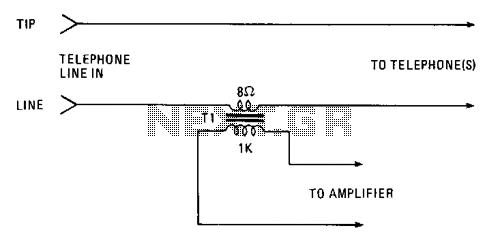
Amplify or record a telephone call using the simple circuit illustrated. The 8-ohm secondary winding of a miniature transistor output transformer is connected in series with one of the telephone lines. The 1000-ohm primary winding can be used to...
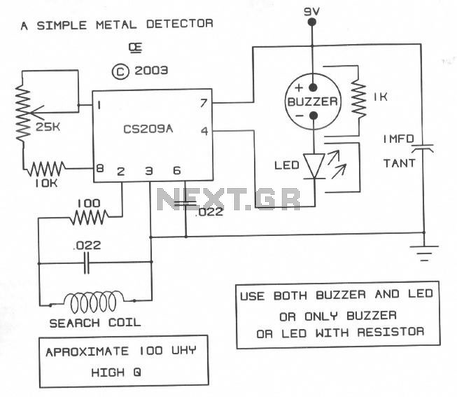
A simple design based on a CS209A IC that can give surprising results and draws very little current from a 9-volt battery. It worked well on the bench but not so good outside for general metal detecting. However, it...
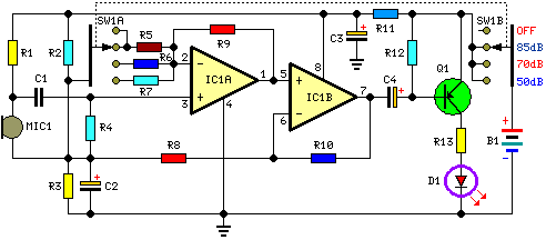
This circuit is designed to indicate, via a flashing LED, when room noise exceeds a predetermined threshold, selectable from three fixed levels: 50 dB, 70 dB, and 85 dB. The circuit utilizes two operational amplifiers to amplify the sound...
A ringer interface circuit is designed to buffer the output of a central telephone system, which connects to multiple ringers distributed throughout a building. This circuit addresses an issue where the line overloads when ringing, requiring a reset. The...
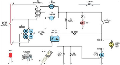
This alarm circuit was designed to monitor a mains-powered smoke detector located in a shed used for housing dog kennels. It provides complete isolation. This alarm circuit is engineered to ensure the safety of a shed environment, specifically designed for...
This circuit is a two-wire light level detector, which does not separate the wires for power supply and output signal delivery. It operates using a current loop that performs both functions over a single pair of cables, requiring only...