
phone hold circuit

The hold feature circuit designed for use with traditional bell phones is an essential addition for users who wish to enhance their calling experience. The circuit typically involves a relay or a transistor switch that engages when the hold button is pressed. This mechanism interrupts the call while maintaining the line connection, allowing the user to attend to other matters without disconnecting.
The circuit can be constructed using a few common electronic components, including resistors, capacitors, diodes, and a relay or transistor. The relay acts as a switch that opens the line to the receiver while keeping the connection active on the line. A small capacitor can be used to filter any noise and stabilize the power supply from the phone line, ensuring that the circuit operates smoothly without interruptions.
Installation of the circuit inside the phone requires careful consideration of space and accessibility. The components should be arranged neatly to avoid interference with the phone's existing wiring. The power supply, drawn from the phone line, typically requires no additional power source, making the circuit energy-efficient and convenient.
Overall, this hold feature circuit represents a practical solution for users of original bell phones, providing a modern functionality while maintaining the integrity of the traditional device. Its compact design and reliance on the phone line for power make it an ideal modification for enhancing communication capabilities.Although a hold feature is standard on most new phones, a lot of us still use the origional bell phones. Those of us that require a hold feature will find this circuit very useful. It is easy to build, and is compact enough to be installed inside the phone with no real problem. It is also powered by the phone line itself, eliminating the need for batteries. 🔗 External reference
Related Circuits
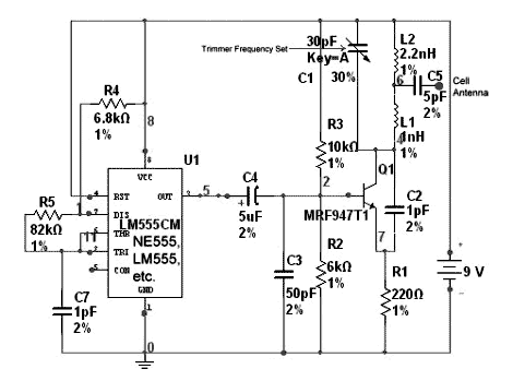
And my recent study about chaos is really making me have FUN! The subject is awesome! And my Geeky Bro informed me something about a cell phone jammer, a simple timer circuit using 555. Will work within 10 feet...
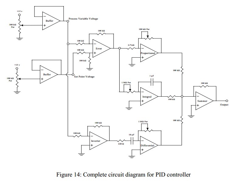
Convert a feedforward operational amplifier PID loop to C code. Assistance is needed for this conversion, as the process is unfamiliar. Input values can be obtained through an ADC, such as voltage or current, but coding a feedforward PID...
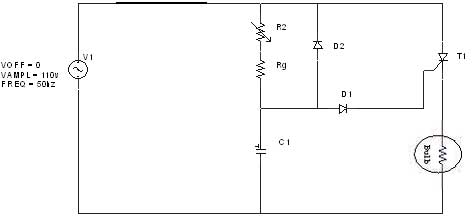
The diagram illustrates an R-C-Diode circuit that provides full half-cycle control (180 electrical degrees). During the positive half-cycle of the SCR anode voltage, the capacitor charges to the trigger point of the SCR, a process governed by the RC...
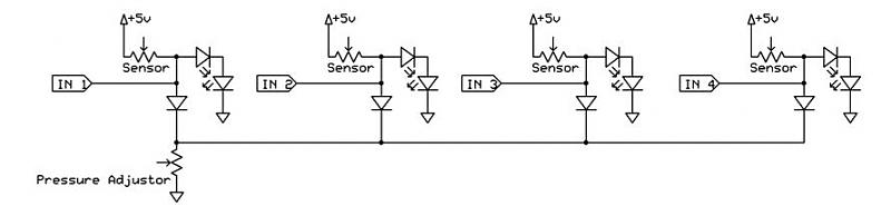
A dance pad consists of four pressure sensors (up, down, left, right). A USB controller has already been created for the dance pad, and the next step involves connecting the actual sensors. The intention is to pull the input...
The amplifier's gain is nominally 20 dB. Its frequency response is primarily influenced by the values of a few components, mainly C1 and R1. The schematic diagram's component values yield a frequency response of ±3.0 dB from approximately 120...
The 27MHz crystal oscillator circuit is illustrated in the figure. Resistors R1, R2, and R3 serve as biasing resistors, while capacitor C6 functions as a bypass capacitor. The voltage division circuit consists of capacitors C1, C3, C4, and C2,...