
27MHz crystal oscillator circuit

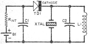
The 27MHz crystal oscillator circuit is designed to generate a stable frequency output, primarily used in various communication and timing applications. The circuit operates by utilizing a quartz crystal, which exhibits a precise resonant frequency. This crystal is connected in parallel with the circuit components, allowing it to control the oscillation frequency effectively.
The biasing resistors R1, R2, and R3 are critical in setting the operating point of the active device, ensuring that the oscillator remains in the correct region of operation. These resistors help stabilize the gain of the amplifier stage, which is essential for maintaining consistent oscillation.
Capacitor C6, acting as a bypass capacitor, provides a low-impedance path to ground for high-frequency noise, thereby improving the stability and performance of the oscillator. The voltage division circuit, composed of capacitors C1, C3, C4, and C2, plays a vital role in determining the feedback path of the oscillator. By adjusting these capacitors, one can fine-tune the amplitude of the oscillations, which is crucial for achieving the desired output signal strength.
Inductor L1, as a high-frequency choking coil, is employed to filter out unwanted high-frequency signals from the power supply, ensuring that only the desired frequency passes through the circuit. This filtering action helps to minimize noise and improve the overall performance of the oscillator.
The combination of these components creates a robust oscillator circuit capable of delivering a stable 27MHz output, making it suitable for various applications, including RF transmission and clock generation in digital circuits.The 27MHz crystal oscillator circuit is as shown in the figure. The R1, R2, R3 are the biasing resistor, the C6 is the bypass capacitor, the voltage division circuit is composed of the C1, C3, C4 and C2 to control the oscillation strength. The L1 is the high-frequency choking coil which has the filtering effect. The quartz crystal is in the parallel resonan.. 🔗 External reference
Related Circuits
Fast and efficient charging is significantly higher than conventional charging, achieving a current charge that is ten to several times greater. When the battery voltage reaches a predetermined level (known as the polarization point), polarization within the cell becomes...
This circuit automatically activates and deactivates a motorcycle's headlight, functioning independently of both the light and ignition switches, as long as the battery is fully charged. The initial stage employs a 220-ohm resistor and ZD1 to keep transistor Q1...
A display tube utilizing a constant current circuit to ensure a steady flow through the tube. The display tube operates on the principle of maintaining a constant current to achieve consistent brightness and performance. The circuit typically comprises a current...
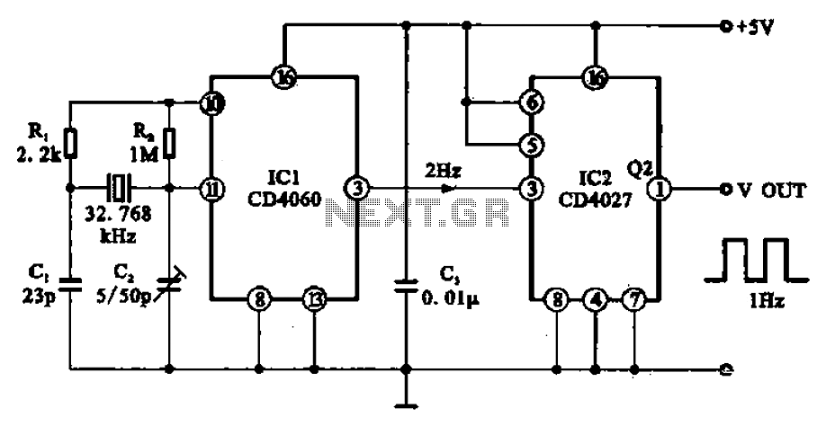
A 1Hz clock signal generator circuit is presented, which demonstrates a sophisticated clock signal generating mechanism. This circuit can be utilized for digital clocks and timing applications. It comprises a binary counter (CD4060), a JK flip-flop (CD4027), and a...
The circuit includes a controller that integrates an acoustic-electric conversion and amplification circuit, a clock pulse generator, a counting circuit, and a control circuit. It manages four accompanying music tracks and flashing lights. Microphones (MIC) convert sound into electrical...
Leo Esaki invented the tunnel diode in 1957 while working at Sony (then known as Tokyo Tsushin Kogyo). Tunnel diodes feature a very narrow, heavily doped p-n junction approximately 10 nm wide, which exhibits a broken bandgap. This configuration...