
rc triggering circuit

The R-C-Diode circuit operates by controlling the timing of the SCR (Silicon Controlled Rectifier) firing, which is crucial for applications requiring precise power control such as dimmers, motor speed controllers, and heaters. The capacitor in the circuit plays a pivotal role, charging during the positive half-cycle and discharging when the SCR is triggered. The RC time constant, defined by the resistor (R) and capacitor (C) values, determines how quickly the capacitor charges to the necessary threshold voltage to trigger the SCR.
During operation, as the SCR is forward-biased in the positive half-cycle, the capacitor charges up to a certain voltage level. This voltage level is dependent on the RC time constant, which is influenced by the resistance and capacitance values selected in the circuit. Once the capacitor voltage reaches the SCR's gate trigger voltage, the SCR turns on, allowing current to flow through the load.
In the negative half-cycle, diode D2 ensures that the capacitor discharges in a controlled manner, preventing reverse current flow that could damage the SCR. The capacitor's voltage can reverse as the supply voltage increases, allowing it to recharge in the opposite direction. This mechanism resets the capacitor for the next cycle, ensuring that the circuit can continuously control the load based on the input voltage waveform.
The ability to vary the firing angle from 0 to 180 degrees allows for a flexible control mechanism, enabling the adjustment of the power delivered to the load. This feature is particularly beneficial in applications where varying levels of power are required, enhancing the circuit's versatility and efficiency. Overall, the R-C-Diode circuit exemplifies a fundamental approach to phase control in AC circuits, providing effective management of power delivery through precise timing of SCR operation.Diagram shows an R-C-Diode circuit giving full half-cycle control (180 electrical degrees). On the positive half-cycle of SCR anode voltage the capacitor charges to the trigger point of the SCR in a time determined by the RC time constant and the rising anode voltage. The top plate of the capacitor charges to the peak of the negative voltage cycl e through diode D2 on the negative half-cycle, resetting it for the next charging cycle. During negative half cycle capacitor charges in reverse direction when the supply voltage increases towards positive side the capacitor voltage also recharges in opposite direction. When this capacitor voltage reaches threshold voltage SCR will turn on and capacitor discharges through diode D2 and its voltage become very small positive voltage.
Firing angle can be varied from 0 to 180 degree. 🔗 External reference
Related Circuits
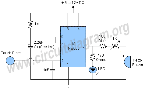
This project features a schematic for a touch alarm circuit. The circuit is highly sensitive and activates a piezo buzzer or any other type of buzzer, along with an LED, for a predetermined duration when a metal plate is...
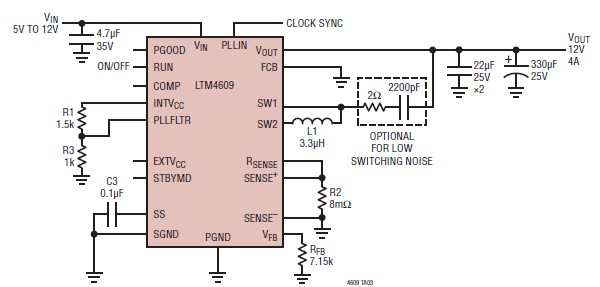
A very simple, high-efficiency switching mode buck-boost power supply circuit can be designed using the LTM4609 switching regulator IC. This circuit will provide a fixed output voltage of 12 volts. As illustrated in the schematic, the switching power supply...
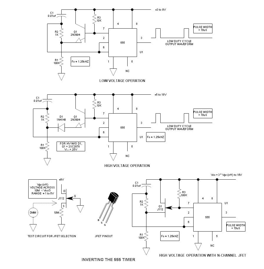
When using the 555 timer, the output polarity often appears to be incorrect, as the 555 typically cannot produce a duty cycle of less than 50%. This inverted 555 circuit is capable of generating duty cycles below 50%. The...
This article offers a circuit diagram and a discussion on CMOS logic and IC layout for creating a set of attention-getting LED running lights. It details a simple sequential LED flasher or light chaser that can be built, including...
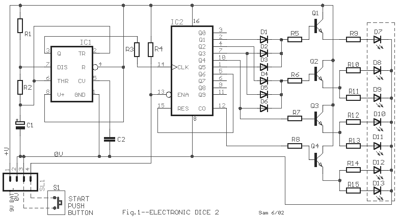
The IC1 is a 555 timer IC configured for astable operation, generating clock pulses that are fed to IC2 through a 10K resistor. IC2 is a 10-stage counter, with output 6 (pin 5) connected to RESET (pin 15), resulting...
This circuit is similar to the LED clock using 12 neon indicator lamps instead of LEDs. It operates from 2 high capacity ni-cad cells (2.5 volts) which keep it going for a couple weeks. High voltage (70 volts) for...