
The thermometer circuit composed of LX5600

The described thermometer circuit employs an astable multiresonance oscillator configuration, which is key to its intermittent operation. The circuit is designed with two transistors, VT1 and VT2, configured to function as a flip-flop. This configuration allows the thermometer to alternate between high and low states, effectively sampling the ambient temperature at one-second intervals.
The choice of an astable multiresonance oscillator is significant as it provides a stable output frequency, which is essential for consistent temperature readings. The internal temperature of the thermometer remains relatively constant, minimizing fluctuations that could affect measurement accuracy. This characteristic enhances the reliability of the temperature test circuit, ensuring that readings reflect the true ambient conditions without sharp variations.
The interval time ratio of 0 indicates that the oscillator is continuously operating without a defined pause, allowing for real-time monitoring of temperature changes. The output from the oscillator can be fed into a microcontroller or analog readout device, where the sampled data can be processed and displayed.
In summary, this thermometer circuit effectively combines an astable multiresonance oscillator with a stable temperature measurement system, ensuring accurate and reliable temperature readings in a room environment through its intermittent operational capability.When this thermometer is used in the room, it can work in the intermittent way, and this working state can be kept in the temperature test circuit, because internal temperature doesn`t change sharply. The astable multi-resonance oscillator consists of VT1 and VT2, i.e the interval oscillator circuit, which samples per 1s, and the interval time ratio is 0..
🔗 External reference
Related Circuits
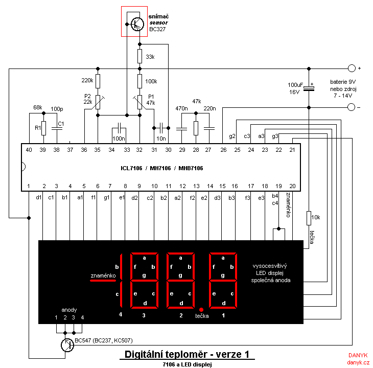
Two versions of a homemade digital thermometer utilizing the ICL7106 are presented. One version features an LED display, while the other employs an LCD display. Both variants utilize a silicon transistor as a temperature sensor, with temperature determined by...
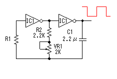
This circuit is a square wave oscillator that utilizes CMOS-type logic inverters. The term "logic inverter" is used to prevent confusion with a DC/AC inverter. The oscillator's output is connected to a drive circuit via the logic inverters. The...
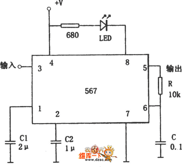
The figure illustrates the 567 FM demodulator circuit. The FM signal is received at pin 3, while the demodulated output signal is available at pin 5. The central frequency of the FM signal that the circuit can demodulate is...

This circuit is a six-band graphic equalizer that allows modification of sound across low, mid, and high frequencies using an IC 741 operational amplifier. It enables management and mixing of frequencies and tones as desired. The audible frequency spectrum...

The LED operates at 3V, and based on information available online, a blue LED typically supports a maximum current of 0.03A. Given the available current from the USB source, the intention is to construct a parallel circuit. However, the...

A DC brush motor driver circuit diagram utilizing the MC33035 chip is presented, illustrating a typical configuration for driving a straight DC brush motor. The circuit incorporates a field-effect transistor (FET) bridge driver setup. When transistor VT3 is activated,...