
phone tap circuit

The circuit described is a basic audio recording device designed to capture conversations on a telephone line. It employs a simple resistor-capacitor (RC) network to facilitate the recording process without significantly disrupting the normal operation of the phone line. The circuit's simplicity is one of its key advantages, as it reduces the potential for faults and makes it easier to troubleshoot.
The primary components of the circuit include resistors R1 and R2, which are critical for determining the circuit's impedance and load on the phone line. The values of these resistors can be adjusted to match the specific characteristics of the phone line, which may differ from one installation to another. A suggested value of 2.47K ohms for the combined resistance of R1 and R2 can help optimize the circuit's performance when connected in parallel with the phone line, ensuring that it can capture audio from multiple devices.
Incorporating a 2.2μF capacitor in place of the resistors is an alternative approach that can enhance the circuit's functionality. This modification effectively blocks direct current (DC) components from interfering with the phone line while allowing alternating current (AC) signals, which carry the audio information, to pass through. This adjustment reduces the risk of the phone line being held off-hook, thereby maintaining normal telephone operation.
The circuit can be installed discreetly, allowing for unobtrusive monitoring of conversations. However, it is essential to consider legal implications and obtain necessary permissions before recording any conversations, as laws regarding audio recording can vary by jurisdiction. Overall, while the circuit provides a straightforward solution for recording telephone conversations, careful consideration of component values and installation practices is necessary to ensure reliable operation.This circuit is extremely simple, therefore there is less chance of any problems. It can be placed anywhere on the phone line and it will record any conversation on any phone on that line. Please note: I have received several emails saying that this circuit will not work and that it may hold your line off hook and to me it looks like it will (it w
ould put quite a load on the phone line). For some, it has worked fine. Build at your own risk. The values of R1 and R2 may have to be adjusted, depending on the characteristics of the phone line it is connected to (they vary). If the R1+R2 combination is increased sufficiently (try 2. 47K) then the circuit can be connected in parallel with the line, thus covering all attached devices.
(Thanks to Mark Wright for the suggestion). T. A. Betts offers this suggestion for getting this problematic circuit working: "If you drop the resistors and add a 2. 2uF capacitor the line will not stay off hook. It blocks the DC from the moniter position. " 🔗 External reference
Related Circuits
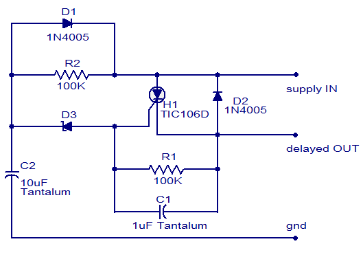
The circuit diagram presented is of a straightforward DC power delay circuit utilizing a silicon-controlled rectifier (SCR). This circuit is quite useful and can be applied in various scenarios. The operation of this circuit is uncomplicated. Upon the application...

This circuit is designed for general-purpose use with a large LED display utilizing SPI serial interfacing. It employs a serial-in-parallel-out shift register, specifically the 74HC595, to receive serial data from a microcontroller board. The schematic wiring indicates that SER...
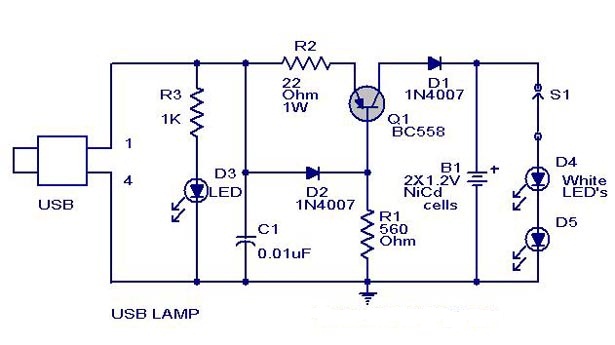
A simple USB-powered lamp designed to illuminate a desktop during power outages. The circuit operates at 5 volts sourced from a USB port. The 5V from the USB is directed through a current-limiting resistor (R2) and a transistor (Q1)....
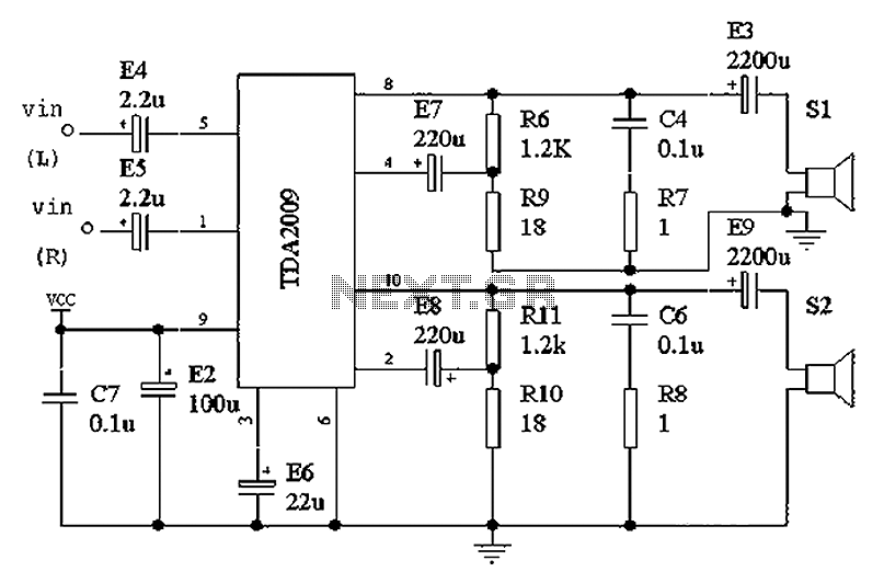
The intention was to develop a morning exercise machine, but the challenge was the absence of a suitable high-power amplifier. Since the exercise machine operates on battery power, the search for a solution persisted for several months. Eventually, the...
Power an RS232-TTL converter circuit using the serial port to eliminate the need for an external power supply. It has been noted that the DTR, RTS, and TD pins can facilitate this. Since the TD pin is already utilized...
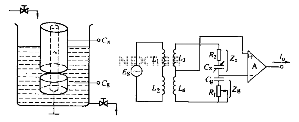
The capacitance change in a capacitive sensor is directly converted into electrical parameters, which are then unified for signal transmission, processing, and display. These electrical parameters can be categorized into resistive, capacitive, and inductive types. This explanation focuses on...