
Capacitive level measuring circuit

The capacitive level meter operates under the principle of capacitance variation due to changes in the dielectric medium between the capacitor plates. The sensor typically consists of two conductive plates separated by a dielectric material, which can be air, liquid, or solid. When the level of a liquid rises, the dielectric constant of the medium between the plates alters, leading to an increase in capacitance. This change can be mathematically represented by the formula:
\[ C = \frac{εA}{d} \]
where \( C \) is the capacitance, \( ε \) is the dielectric constant of the medium, \( A \) is the area of the plates, and \( d \) is the distance between them. As the liquid level increases, the effective dielectric constant increases, resulting in a higher capacitance reading. Conversely, as the liquid level decreases, the dielectric constant reduces, leading to a lower capacitance.
The measuring circuit designed for this capacitive sensor typically includes a capacitor reference arm (G) and associated electronics that can process the changes in capacitance. This circuit can convert the capacitance value into a readable signal, suitable for display or further processing. The output signal can be analog or digital, depending on the design requirements. In practical applications, the capacitive level meter is widely used in various industries for fluid level monitoring, providing a non-invasive and reliable method for measuring liquid levels in tanks, silos, and other containers. Capacitance/C tuck bit IJ volume level change is directly converted into electrical parameters, electrical parameters and then be converted to a unified signal transmission, pr ocessing, display and so on. The electrical parameters can be divided into different: resistive, capacitive and inductive and so on, now capacitive for the introduction. We know that the most simple capacitor capacitance from the above equation by changing the t d, E or A change of approach could be made, respectively, the corresponding capacitive sensor.
Capacitive level meter consists of capacitive sensors and measuring circuit. Capacitive sensors by changing the dielectric constant E of the general principle made, FIG. 6-38a, b capacitive liquid level sensors and measuring circuits. In setting a cylindrical capacitor test solution at the plate area A and distance d is fixed, the capacitance Velvet C. The dielectric medium between the plates with dielectric constant E change. Let the liquid dielectric permittivity, Tuen constant gas is e2, general E, ez, when the liquid level rises, the total dielectric constant increases.
Thus the capacitance G increases, and vice versa, when the level drops Rang, E decreases. c, decreases. It is possible that by measuring the C rhyme change the level of liquid in the container. Figure 6-38b capacitance measuring circuit, G is the reference arm capacitance.
Related Circuits
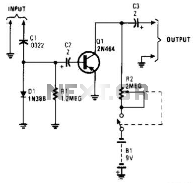
In this circuit, C1, D1, and R1 form an envelope detector. C2 couples audio to the base of Q1. R2 can be adjusted for the desired gain. The circuit under discussion utilizes an envelope detector, which is a fundamental component...
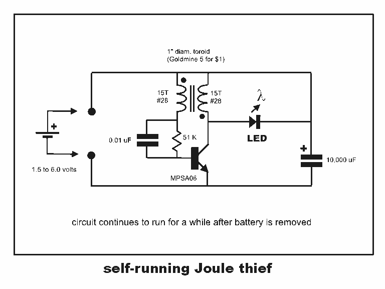
Professor Steven E. Jones' circuit demonstrates an 8x overunity. The concept of overunity refers to a system that produces more energy than is consumed, effectively achieving a coefficient of performance greater than one. In the context of Professor Steven E....
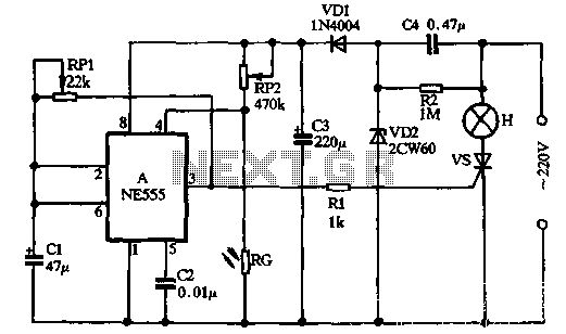
VDI, VD2, C3, and C4 form a simple half-wave rectifier capacitor step-down regulator circuit. This circuit can output approximately 12V DC voltage after power is applied across C3, which is utilized for the time base circuit. Additionally, the time...

This design has not been referred to as a GOLD detector, as that term is reserved for more complex devices capable of distinguishing gold from other metals. There is a significant difference between detecting gold and ordinary metals, known...
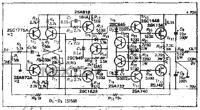
The south circuit consists of four parts, arranged in descending order: an NPN transistor dynamic garbage device (T1), a PNP transistor differential amplifier (T2, T3) forming a double differential circuit, two balanced output amplifiers with opposite phase, and a...
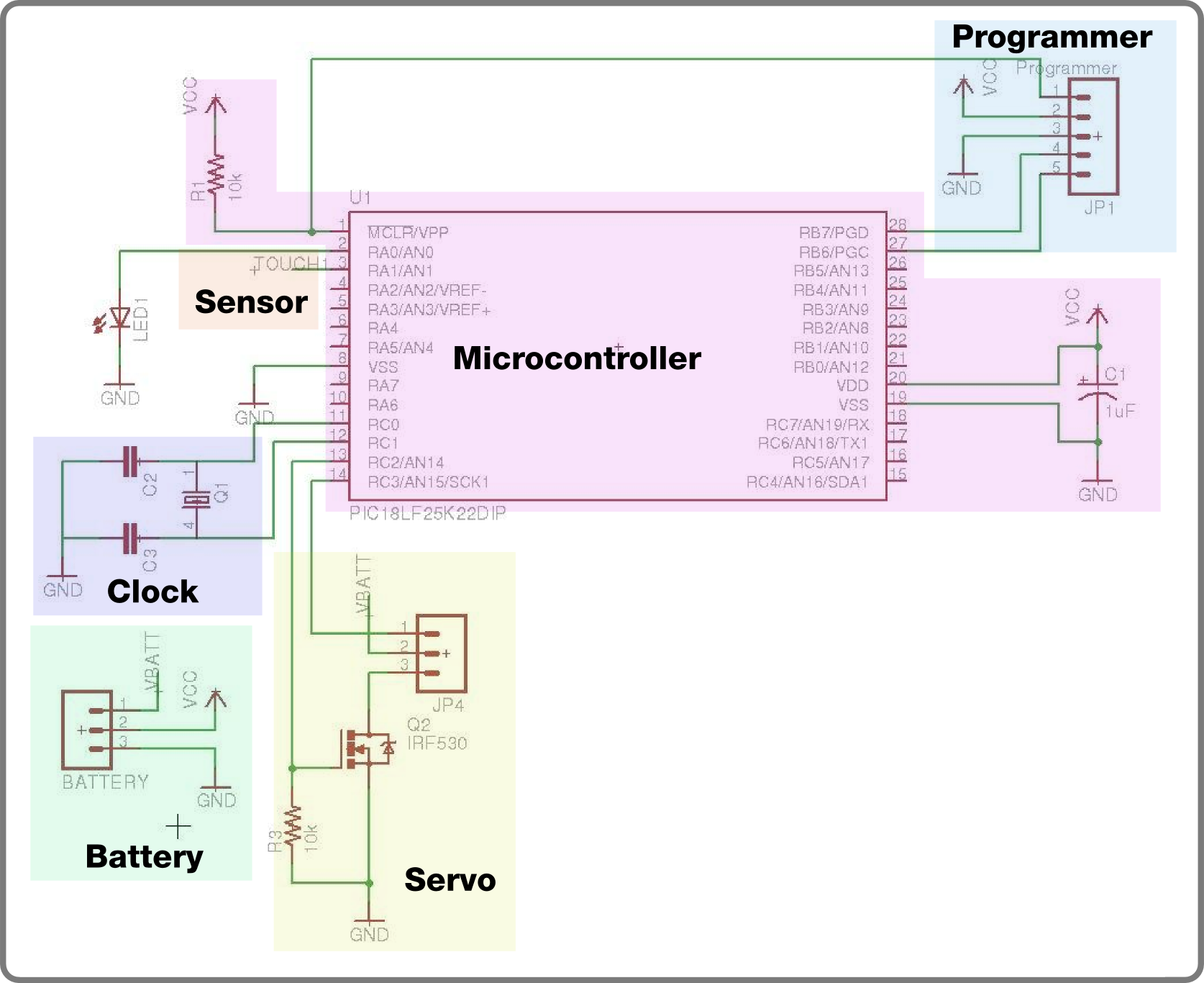
For the second build in the Make It Last Build Series, a robotic plant is being constructed. This week focuses on assembling the control circuit, which will be used in future weeks to animate the plant. The basic circuit...