
Phone to Microcontroller interfacing with DTMF

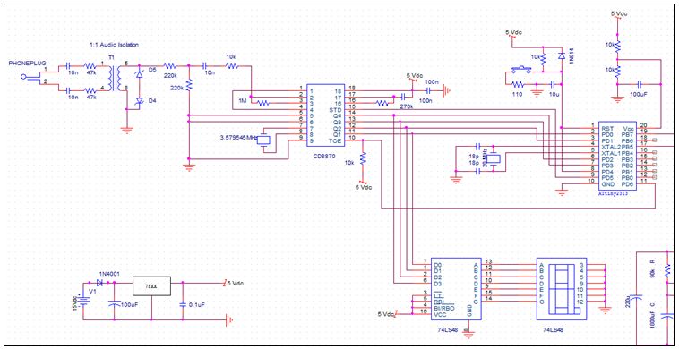
The schematic for this project consists of several key components arranged to facilitate the interaction between the telephone line and the microcontroller. The telephone line connects directly to the MT8870 DTMF decoder, which is the heart of the system. The decoder interprets the DTMF tones and produces a 4-bit binary output that corresponds to the pressed key on the telephone keypad. The outputs Q1 to Q4 of the MT8870 are connected to the ULN 2003 driver, which serves to amplify the signals before they reach the microcontroller. The ULN 2003 is a Darlington transistor array that provides the necessary current and voltage levels to ensure proper operation of the microcontroller inputs.
The ATMEGA-8 microcontroller is programmed to monitor the status signal from the MT8870. When a valid DTMF tone is detected, the interrupt service routine is triggered, allowing the microcontroller to read the binary output and determine which key was pressed. The microcontroller then processes this information and, if the correct command is received, activates the latching relay through the BC108 transistor. This transistor acts as a switch, controlling the power to the relay coil, which in turn engages the relay contacts to control external devices.
The power supply for the entire circuit is stabilized by the IC 7805 voltage regulator, ensuring that the microcontroller and other components receive a consistent 5V power supply. The inclusion of a heat sink on the 7805 is crucial for maintaining performance and reliability during operation. The Magnetic Latching Relay is particularly advantageous in this design, as it allows for the control of high-power devices without continuous power draw, making the system efficient and effective for remote operation.
Overall, this interface system provides a versatile solution for remotely controlling appliances using standard telephone DTMF tones, combining simplicity and functionality in a compact design.How to interface a microcontroller to the phone line. The tones you hear as you enter numbers on your phone can remotely control devices. Learn how to use these DTMF tones in your microcontroller projects. This article was submitted by Mayank Magoo as part of the Hobby parts for articles program. Mayank received a Arduino compatible Modern Device Company Bare Bones Kit for this great article. This project describes the development of a system to interface the telephone line with a microcontroller. Using this interface any device can be controlled using a telephone or cell phone. The system involves the use of DTMF tones commonly used in telephone networks. Dual-Tone Multi-Frequency ( DTMF ) signaling is used for telephone signaling over the line in the voice-Frequency band to the call switching center.
These are the tones you hear when you dial a touch tone phone. The standard DTMF keypad is laid out in a 4G—4 matrix, with each row representing a low frequency, and each column representing a high frequency. Pressing a single key will send a sinusoidal tone of the two frequencies at the same time, the lower frequency for the row of the pressed key and the higher tone for the column.
These tones are then decoded at the receiving end to determine which key was pressed. The use of two tones for a single key ensures that no two keys will generate the same signal. There are 16 possible tone sets but only 12 are used on common telephones. The ATMEGA-8 microcontroller was selected due to it`s low cost and it`s 8Kb of programmable flash memory and 512 bytes of EEPROM and ease of programming and implementation. The MT8870 is a low cost DTMF Decoder which gives a 4-bit binary output characteristic of each tone and a status signal which has logic high whenever a valid DTMF tone is received.
The Q1 to Q4 outputs produce a 4 bit binary output corresponding to each tone. The StD output signals that a valid tone is present. The IC 7805 is a linear voltage regulator. It provides a constant +5 voltage in spite of the variations in the incoming voltage. Each IC 7805 is connected to a heat sink to dissipate heat. The Magnetic Latching Relay has 10-pin contacts and two separate pins for latching and unlatching the relay. The relay once latched will remain latched even if the power is removed thereby reducing the power requirements and provide and easy and effective way to cut-off the ignition.
Telephone line is connected to the MT88770 DTMF Decoder, the 4-bit decoded binary output is connected to ULN 2003 Bridge whose output is fed into the micro-controller. The status signal from MT8870 is used to trigger an interrupt whenever a new DTMF tone is detected. The microcontroller then reads the decoded output. Once the correct code is received, the microcontroller activates the latching relay via the BC108 transistor.
Power for almost any appliance could be controlled this way. 🔗 External reference
Related Circuits
The main system consists of the user interface and control system. The phone line was selected as the interfacing method due to its advantages in long-distance communication. The subsequent image provides a block diagram for both the remote access...
The telephone ring generator illustrated below produces the necessary high voltage using a simple switching mode power supply (SMPS) that incorporates a CMOS Schmitt Trigger square wave oscillator, a 10 mH inductor, a high voltage switching transistor (such as...
This circuit diagram illustrates the conversion of a speaker into a microphone. When sound waves impact the diaphragm of a speaker, fluctuations occur in the coil, generating an induced voltage. This induced voltage is typically substantial but low in...
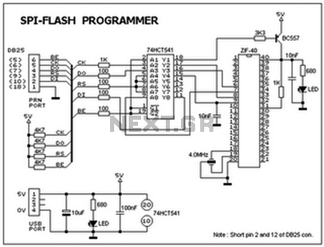
This ISP programmer can be utilized for both in-system programming and as a standalone SPI programmer for Atmel ISP programmable devices. The programming interface is compatible with the STK200 ISP programmer hardware, allowing users of STK200 to employ the...
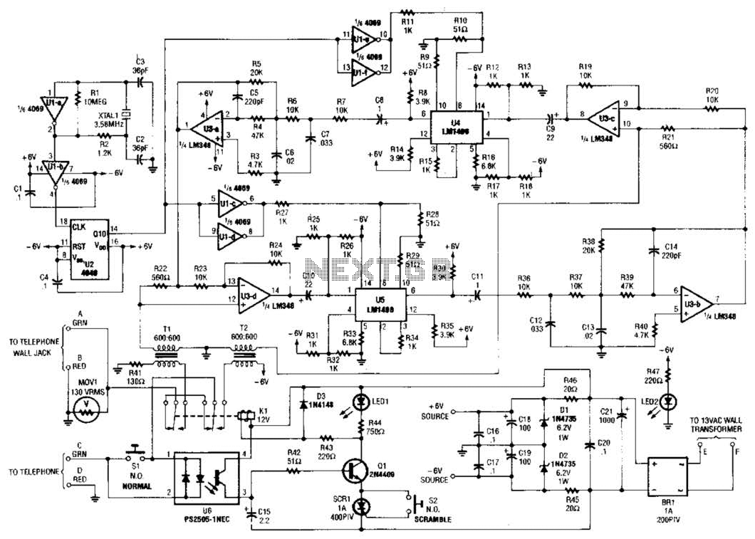
Two hybrids (T1 and T2) are utilized to facilitate a direct connection to a telephone line. This circuit employs a standard speech-inversion algorithm, which inverts the frequency of an audio signal around a central frequency. An LM1496 balanced modulator...
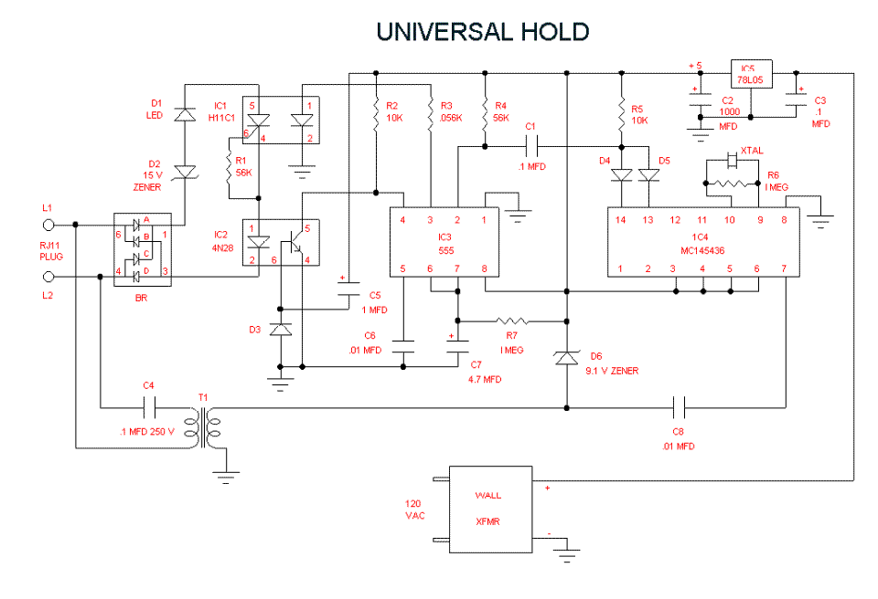
The UNIVERSAL HOLD circuit detects the dual tone, multi frequency (DTMF) tone that is generated when the # key is pressed and then activates a circuit that partially loads the telephone line so that the central office thinks a...