
dtmf decoder

The system architecture emphasizes a robust user interface that leverages DTMF technology for remote control. The DTMF decoder is a critical component, converting audio signals into digital data that the microcontroller can process. This decoder must be capable of handling the audio frequency range associated with DTMF signals, typically 697 Hz to 1633 Hz, ensuring accurate signal interpretation.
The microcontroller, acting as the system's brain, is programmed to manage user inputs, validate access codes, and control subsystem activation. It is essential for the firmware to include debouncing logic for the key presses, ensuring that noise or accidental multiple presses do not lead to erroneous inputs. The memory management for the last four signals is a sophisticated feature that prevents overflow and maintains a clear record of user inputs.
The lockdown feature enhances security by temporarily disabling access after multiple failed attempts, a crucial aspect for preventing unauthorized entry. The inclusion of a clear function via the star key provides users with a method to reset their input without the risk of triggering the lockdown.
Subsystems are designed to be modular and independent, allowing for flexibility in system design and future expansions. Each subsystem's ability to operate autonomously through local activation switches enhances usability, making the system adaptable to various applications.
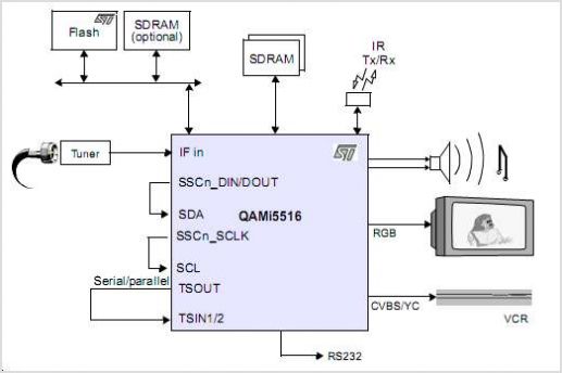
Overall, the system is designed to provide a reliable and user-friendly interface for remote control, with security measures in place to protect against unauthorized access while allowing for easy operation and subsystem management. Future enhancements, such as the RS-232 interface and the DTMF display, will further expand the system's capabilities, allowing for greater interaction with external devices and improved user feedback.The main system is the user interface and control system. The phone line was chosen as the method of interfacing because it has distinct advantages over other systems in communicating information from a distance. The next image serves as a block diagram for not only the remote access interface but the overall system as a whole.
System flow and act ivation begins at the top left of the block diagram with the answering machine picking up a call from the user dialing in remotely. The answering machine controls the connection and disconnection of the phone line to the DTMF decoder automatically.
The user presses the keys on their touch tone enabled telephone in a specific sequence. The DTMF decoder circuit is connected to the phone line and it interprets the DTMF signals on the line and forwards them to the main microcontroller in the form of a four bit binary number. The controller running the main firmware determines if the correct input sequence was entered by the user and interfaces directly with the individual subsystems.
The subsystems also have a local activation capability such as a pushbutton switch to control its functionality. The subsystems are independent of one another and can operate in parallel if an activation signal is given from either the controller or from the local activation switches.
The RS-232 interface with the computer and the decoded DTMF display are both examples of future work for the system and are not implemented on the prototype. The open air microphone also shown in the block diagram has been removed for lack of relevance and because of the noise it introduces on the line.
The flow of the microcontroller software is shown below. When a user dials into the system remotely they are in the user interface portion of the system flow. DTMF signals are decoded and forwarded to the microcomputer processor. The microprocessor stores the last four signals received in memory. If more than four button presses are detected the microprocessor begins again writing over the first button press stored in memory.
For example, if the sequence entered by the user was: This is because of the previously described wrap around effect built into the program software. When the user has entered what they believe to be the correct code the pound key (#) is pressed on the phone pad and the microprocessor looks at the code it has stored in memory as described above.
The received code is then compared against a firmware defined code. If the code does not match, the software begins counting the failed access attempts. If the failed attempt count reaches three, the microprocessor enters a three minute lockdown mode where further remote access to the system is denied. This lockdown mode is designed to discourage unauthorized access to the system. If the user believes that they have pressed a wrong key, they can clear the code stored in memory by pressing the star (*) key with no penalty.
If the pound button is pressed and an incorrect code was entered, there is no way for the user to delete the failed attempt, except by hanging up and redialing. If the system is in lockdown mode when a person attempts to dial in the system, it will not respond until the three minute lockdown has finished running its course.
Once the correct code sequence has been entered and confirmed correct by the microprocessor, the user is granted access to activate any number of the desired subsystems. The subsystems are numbered 0-9, *, and #. The subsystem to activate is chosen by DTMF decoding just as the code was entered. At this point in the program any key press will activate a subsystem and a subsystem can be activated multiple times if the user desires.
As the subsystems are self contained, they only require a pulse to begin their respective tasks. To disconnect from the system, the user simply hangs up the phone that they are calling from. The subsystems will finish their jobs with no need 🔗 External reference
Related Circuits
The schematic diagram of the MS Decoder may appear complex, but it is relatively straightforward. Initially, both the Mid and Side signals are buffered using unity gain inverting buffers, which are constructed around IC1b and IC2b. This buffering serves...
500 Series immersion temperature probe, NTC, 100,000 Ohm, ±1.5 °C [±2.7 °F] tolerance, 10 °C to 260 °C [50 °F to 500 °F] accuracy, stainless steel, bullet housing, flying leads (two), 26 gauge Teflon insulation, 4,267 mm [168 in]. The...
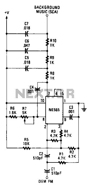
The circuit employs a Signetics NE565 Phase-Locked Loop (PLL) as a detector to recover the SCA signal. The input to the SCA decoder circuit is connected to an FM receiver at a point between the FM discriminator and the...
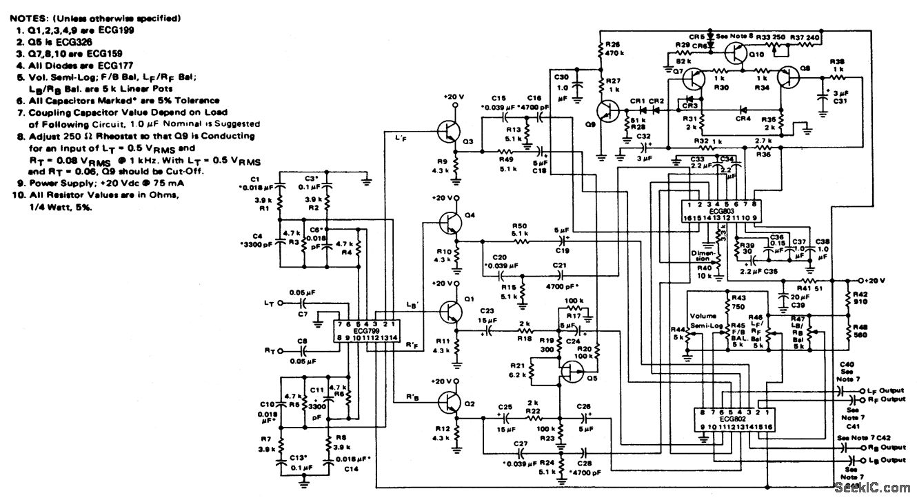
4-channel SQ logic decoder with a current drain of 75 mA at 20 volts. The input impedance is 2M ohms, and the output impedance is 2K ohms (courtesy of GTE Sylvania Incorporated). The 4-channel SQ logic decoder is an integrated...
This project has an impractical requirement or utilizes components that are no longer available. It is provided for reference or inspiration only and is considered unsupported. The project displays telephone numbers decoded from tones, specifically telephone touchtones or Dual...

The IR Widget captures infrared signals used by remote controls and can determine the carrier frequency while demodulating it in either the digital or analog domain. The captured data can be utilized to reproduce or recognize the signal. The...