
phono and line preamp

The described phono preamp circuit is a two-stage cascaded passive RIAA equalizer designed to enhance audio playback quality while minimizing the adverse effects of negative feedback. The circuit's architecture employs a careful selection of components to optimize performance, particularly focusing on the use of specific vacuum tubes known for their linearity and sound fidelity. The choice of using Ni-MH batteries for cathode biasing indicates a commitment to improving sound detail and clarity, which is crucial in high-fidelity audio applications.
The circuit's design emphasizes maintaining an appropriate load impedance, which is critical for preserving the integrity of the audio signal across the frequency spectrum. The recommendation to avoid cathode followers aligns with the goal of achieving a pure signal path, ensuring that the audio output remains true to the source material. The use of a high-quality potentiometer, such as the Alps 250K, further underscores the importance of precision in volume control, contributing to channel balance and overall sound quality.
The transition from ECC83/12AX7 to 6SL7/5691 tubes reflects an evolution in design philosophy, with a focus on maximizing bandwidth and depth in audio reproduction. The exploration of alternative high transconductance tubes, while not yielding favorable results in this instance, highlights the subjective nature of audio preferences and the importance of personal taste in circuit design.
In terms of MC cartridge compatibility, the inclusion of a transformer step-up device is a practical solution for elevating signal levels, allowing for seamless integration with MM preamps. The exploration of a direct-coupled cathode follower configuration demonstrates an innovative approach to minimizing output impedance, which is vital for interfacing with various cable types without compromising sound quality.
The acknowledgment of the Tango NP216N transformer and its limitations in bandwidth illustrates a thoughtful consideration of component selection, ensuring that the circuit meets the demands of professional audio applications. The potential for future experimentation with this topology in different contexts, such as a tube microphone preamp, indicates ongoing exploration and adaptability in the pursuit of optimal audio performance. Overall, this circuit design reflects a comprehensive understanding of audio engineering principles, emphasizing the balance between theoretical knowledge and practical application in high-fidelity sound reproduction.I have been hacking the Dyna PAS chassis with various cascoded and cascaded phono circuits all employing negative feedback RIAA EQ in search for a circuit that will satisfy my musical requirements. My research ended when I discovered thisunglamorous2-stage cascaded passive RIAA EQ phono preamp circuit at the back page of an RCA t
ube manual. The most important lesson I learned in this excercise isnegative feedback chokes the sound!I did not alter any component values except for using Ni-mH batteries for cathode bias which I thought improved detail and definition. I strongly advice against the use of a cathode follower and make sure the circuit drives aminimum load of 220Kas originally specified otherwise you will lose bandwidth at both frequency extremes.
I use an Alps 250K but have also tried the cheap Alpha 250K dual log taper carbon pot sold by AES. It does not have the tracking precision of Alps but at normal volume settings the channels are balanced enough. I have been using this phono circuit since the early 90s starting with aPAS chassiswith Telefunken ECC83/12AX7.
Through the years I developed fondness for octals and nowadays I almost exclusively use 6SL7s/5691s which further improved the bandwidth and depth due to its slightly greater transconductance, vis-a-vis, the 12AX7. There are people who swear by using high transconductance tubes like WE417A or 6DJ8. To hear what this was all about, I bread boarded a famous circuit using these tubes but did not find the sound as appealing, must have been just a matter of taste.
I find the superior linearity of true audio tubes like a 12AX7 or even better yet 6SL7 octals play a lot more LPs. For MC cartridge use a transformer step up device like this Tamura TKS-83 or mic transformer to boost the signal to MM level.
I am not a fan of active MC stages and rather not go there. Another very simple topology with a single gain stage direct coupled to a cathode follower. Originally I was just using a 6SN7 dual triode for both stages but was inspired by the Berman article in SP 13 to try a type 76 as the gain stage. I use a lower B+ supply and run the tube at lower plate dissipation and also prefer the sound with the 2.
2K cathode bias bypassed with a 100uf/16V cap [in this case I can justify using Black Gate]. At this signal level the direct coupled 6SN7 cathode follower is sonically beneficial and the low output impedance results in less interaction with long and/or capacitive interconnect cables. [Cable geeks take note: many times the "difference in cable sound" you hear is more a function of load/capacitance especially if your preamp does not have low output Z].
I briefly flirted with this design as a linestage and in spite of the fact that all my SETUP friends liked the sound [whose ears I respect], I eventually went back to the above linestage. The Tango NP216N is a wonderful piece of iron although I have to admit that I needed greater bandwidth than it has to offer.
However this is a circuit that offers a solid 600 ohm [as used in studios] output impedance and can even be wired in balanced mode. At some point I may try this topology again at the output of a tube microphone preamp project. Please do not take my seeming lack of enthusiasm as a dismissal of this topology. I included this schematic because it may well be appealing to other ears and/or applications. 🔗 External reference
Related Circuits
The Line Following Robot sensor, also known as a surface scanner for robots, is a compact, stamp-sized infrared proximity detector that operates within a short range of 5-10 mm. It is based on a standard reflective opto-sensor, the CNY70...
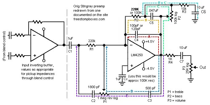
The schematic presented is for the original Music Man Stingray bass guitar preamp. It operates on a 9V DC power supply, and the voltage divider section has been omitted. The Music Man Stingray bass guitar preamp circuit is designed to...
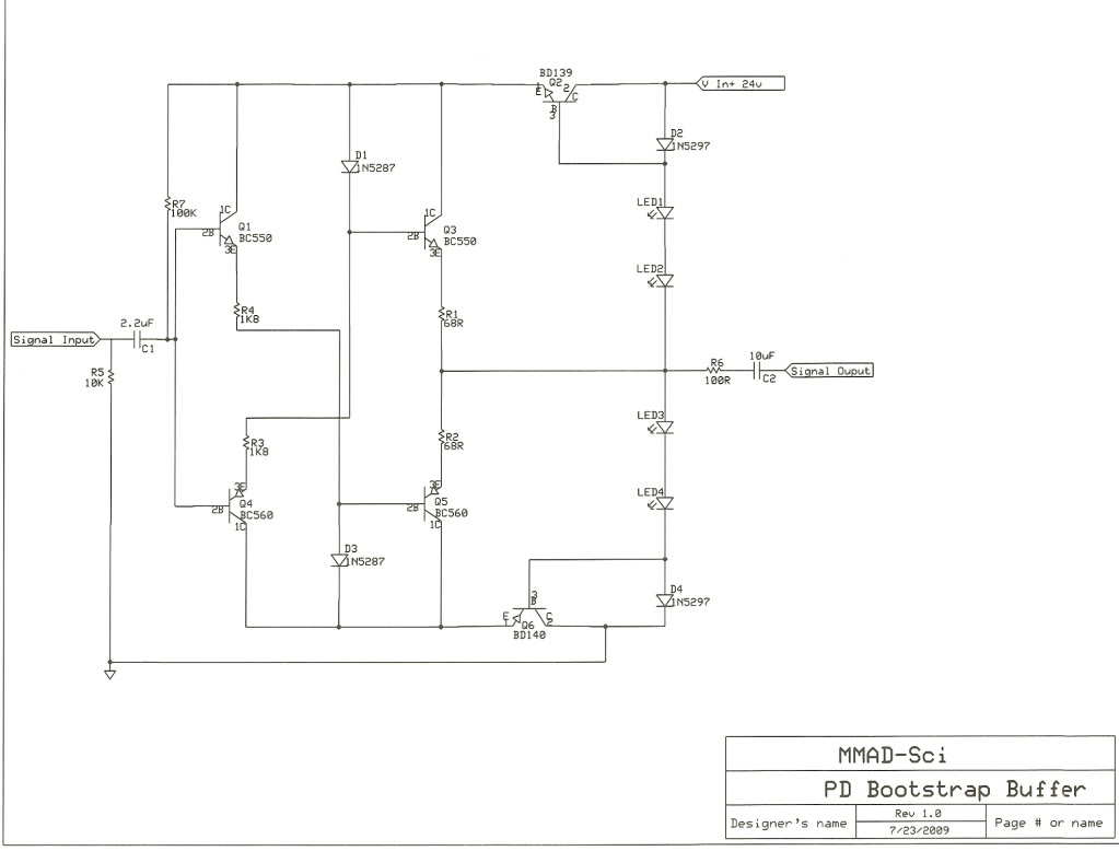
Various circuit variations have been explored, including a standalone preamp, headphone amplifier, replacements for the 321/729 circuits, and a potential active crossover, depending on demand. There has been significant interest in these designs, and the bootstrap buffer preamp is...
This analog switch circuit is designed to switch an analog line on or off. It consists of two analog switches in integrated circuit (IC) form that are controlled by two pushbuttons. The described analog switch circuit utilizes two integrated analog...
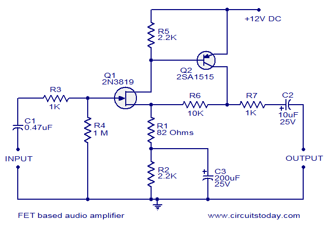
This circuit is a low-noise audio preamplifier that utilizes one FET and one BJT. The audio signal to be amplified is connected to the base of FET Q1 through capacitor C1 and resistor R3. The base of transistor Q2...
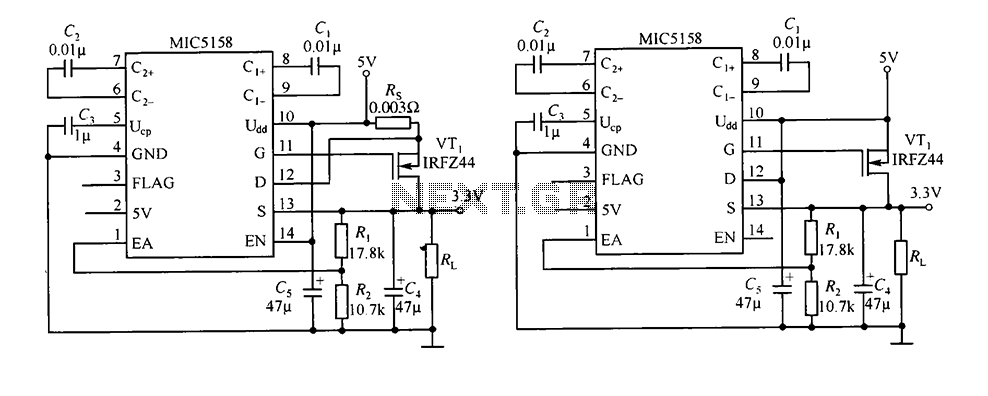
The circuit consists of peripheral components for the MIC5158, a linear regulator that converts a 5V input into a 3.3V output with a maximum current of 10A. When the input voltage (Ui) is 5V, an N-channel MOSFET, specifically the...