
Automatic Rain Sensing Wiper System using 555 Timer

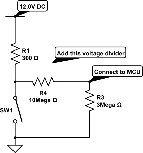
The rain-sensing wiper system utilizes a 555 timer IC in monostable configuration to create a reliable and efficient mechanism for automatic wiper activation. The two metal sheets act as capacitive sensors that detect the presence of water droplets on the windscreen. When raindrops bridge the gap between these sheets, they generate a change in capacitance that triggers a negative voltage at the timer's trigger pin.
In monostable mode, the 555 timer remains in a stable low state until it receives a trigger signal. Once triggered, the output goes high for a predetermined duration, which can be adjusted by varying the connected resistor and capacitor values. This output is then used to energize a relay through a transistor switch. The transistor, typically an NPN type, is used to amplify the current from the output of the 555 timer to activate the relay coil.
The relay serves as an electromechanical switch that controls the wiper motor. When the relay is energized, it closes its contacts, allowing current to flow to the wiper motor, which starts the wiper operation. The duration of wiper operation can be customized by adjusting the timing components of the 555 timer circuit. This design ensures that the wipers operate only when rain is detected, thereby conserving energy and enhancing driver visibility during adverse weather conditions.
In summary, the rain-sensing wiper circuit effectively combines the 555 timer IC, capacitive sensing technology, and relay control to create a responsive and automated wiper system that enhances vehicle safety and convenience.Have you seen Audi, Lexus or Ford rain sensing wipers and wondered how they work in these vehicles They are handled by sensors at the center of the windscreen which detects rain water and turns on the wiper motor. Here is the working of rain sensitive wipers with circuit schematic. The main component of this circuit is a 555 timer IC that works i n monostable mode. Two metal sheets fixed at a small distance apart are used as rain detector sensors. From the working of a monostable 555 timer, a negative voltage on the trigger pin will cause a high output. So when it rains, trigger pin gets a negative voltage. Output of one shot 555 (monostable) is connected to a relay through a transistor. The transistor acts as a switch for the relay to turn ON the wiper motor during rain. 🔗 External reference
Related Circuits
This article describes a 2-Input alarm developed on the PIC LICK-1 Module using a Microchip PIC16F628-04. The program uses the internal 4MHz oscillator and if any other frequency is used, the timer values will need to be changed. A...
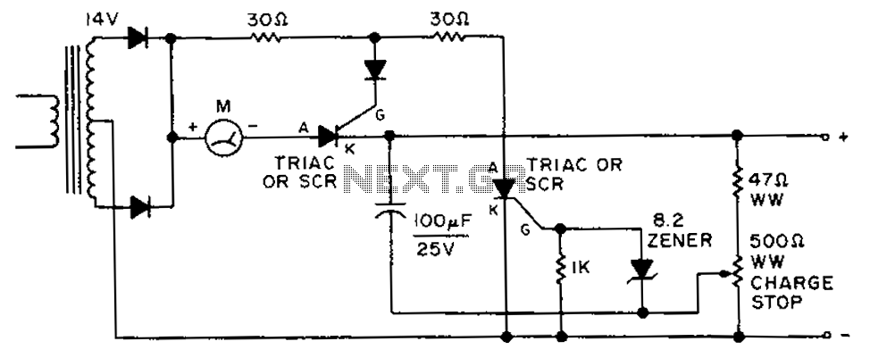
By adjusting the circuit with a 500-ohm resistor, the resistor is integrated into a fully charged battery system. The circuit described involves a 500-ohm resistor that plays a crucial role in regulating the operation of a fully charged battery system....
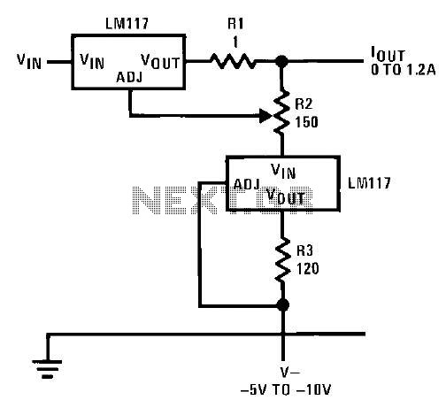
This circuit illustrates an adjustable regulator configuration that incorporates a voltage regulator. In this design, the LM117 regulator is utilized instead of the LM113 diode for reference. Both regulators necessitate a negative supply to function correctly with respect to...
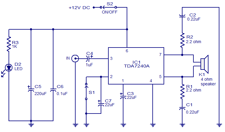
The audio amplifier presented here is based on the TDA7240 integrated circuit from ST Microelectronics. The TDA7240 is capable of delivering 20 watts of audio output power into a 4-ohm load. It requires a minimal number of external components...
The loads consist of two or more solenoids connected in parallel, sharing a 12V supply. Each solenoid is individually switched to ground through the vehicle's ECU. The objective is to detect when any one of the circuits closes, ensuring...
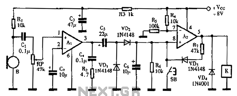
A practical voice-activated switch is presented. An A1 amplifier is connected to a conventional microphone (B) that picks up the audio control signal, which is then amplified. After amplification, the signal passes through components C5, VD1, and VD2, forming...