
Light Switch with 555 Timer

In case you need to trigger something when the gate is blocked (for example, a burglar alarm, or a multistage coilgun), you need to invert the output, which is accomplished using a small bipolar transistor wired in an inverting setup (see pic) or swapping the positions of the phototransistor with the resistor, so the voltage will drop under VCC/3 when blocked: The formula to determine the resistance to turn off at Icollector is R = VCC/(Icollector*3).
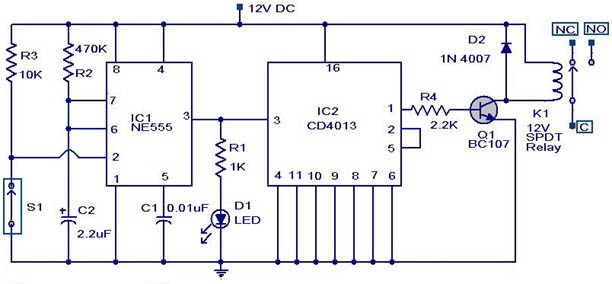
The circuit utilizes a phototransistor as the primary sensor component, which is sensitive to infrared (IR) light. When IR light is incident on the phototransistor, it enters the conductive state, allowing current to flow through a connected resistor, typically valued at 1 MΩ. This current flow results in a voltage drop across the resistor, which is directly related to the collector current (Icollector) of the phototransistor. The voltage at the junction of the resistor and the phototransistor is monitored and compared to a reference threshold level set by the 555 timer IC.
The 555 timer is configured in a monostable mode, where it transitions from a low state (0 V) to a high state (VCC) when the voltage at its trigger pin falls below VCC/3. The sensitivity of the circuit can be adjusted by changing the resistor value; a higher resistance will require more light to trigger the 555 timer, while a lower resistance will increase sensitivity. The use of a trimmer potentiometer allows for fine-tuning of this threshold, providing flexibility based on the specific phototransistor characteristics and application requirements.
In applications where the output needs to be inverted, a small bipolar transistor can be incorporated into the circuit. This transistor will be configured to invert the logic level output from the 555 timer, allowing for applications such as alarm systems or triggering mechanisms for devices like multistage coilguns. Alternatively, the positions of the phototransistor and resistor can be swapped, ensuring that when the phototransistor is not illuminated (e.g., when a gate is blocked), the voltage at the trigger pin of the 555 timer drops below the threshold, thus activating the output.
Overall, this circuit exemplifies the versatility and functionality of the 555 timer IC in conjunction with phototransistors, allowing for a wide range of applications in light detection and control systems.When the phototransistor is stroken by IR light it conducts and the voltage between the 1Mohm resistor(arbitrary) and the phototrans drops from VCC to lower values. When the voltage drops lower than VCC/3 the 555 is triggered and goes high (from 0 TO VCC). The amount of light that strike the phototrans necessary to bring his collector to VCC/3 is determined by the resistor (Vdrop = Icollector * R , so , if Vdrop= 2*VCC/3, the resistance needed to set the threshold on current is R=2*VCC/(Icollector*3)).
High sensibility phototrans would need a smaller resistor, and weaker phototransistors higher value resistor, you can also use a trimmer to set the on threshold level with precision. The 555 is proved to be the most versatile and ubiquitous IC all over the world.This is a possible use: simple inverting schmitt trigger.
The time of phototransistor isn't critical. The 555 has high current capability and can drive various devices, such as Bipolars, relays, bipolars+relays, mosfets, mosfets + totem pole , or give a logic output (see pic). In case you need to trigger something when the gate is blocked (for example a burglar alarm, or a multistage coilgun) you need to invert the output, which is accomplished using a small bipolar transistor wired in an inverting setup (see pic) or swapping the positions of phototransistor with the resistor, so the voltage will drop under VCC/3 when blocked: The formula to determine the resistance to turn off at Icollector is R=VCC/(Icollector*3).
🔗 External reference
Related Circuits
The cumulative timer circuit comprises resistor R1 and an internal crystal oscillator, represented in a chart. Resistors R1 and R2 are metal film types, while resistors R3 to R5 are rated at 1/8W and also of the metal film...
This weblog discusses electronic circuit schematics, PCB design, DIY kits, and electronic project diagrams. The circuit diagram presented is for a magnetic proximity switch, which has numerous applications across various fields. The circuit utilizes a magnetic reed switch (S1)...
This circuit is relatively simple yet valuable, providing a high-quality interior light delay feature. This feature is commonly found in modern cars, although the automatic dimmer version is typically reserved for more expensive models. This circuit allows for the...

The drawing below illustrates a multistage light sequencer using discrete parts and no integrated circuits. The idea is not new and I hear a similar circuit was developed about 40 years ago using germanium transistors. The idea is to...
Hobby servos convert DMX signals into mechanical motion. Typically, hobby servos require a pulse with a variable width ranging from 1 to 2 milliseconds, with 1.5 milliseconds representing the center position. The schematic below illustrates a simple voltage-to-pulse-width circuit....
This circuit is a gradual clear/fade switch for a two-wire connection, designed for simple installation. It activates the lights as needed by turning the switch dial upward. A positive supply of 2V is provided through resistor R. The capacitor...