
Photo Flash from cheap camera

This circuit design features a straightforward pushbutton charging mechanism. The primary components include a power source, a pushbutton switch, a charging circuit, and a load. When the pushbutton is pressed, it completes the circuit, allowing current to flow from the power source to the charging circuit. This design is typically employed in applications where temporary charging is required, such as in battery-operated devices.
The circuit may utilize a simple resistor-capacitor (RC) network to control the charging rate and protect the components from excessive current. Additionally, a diode may be included to prevent reverse current flow, ensuring that the power source is not negatively affected when the pushbutton is released.
The load, which could be a battery or a capacitor, will receive power as long as the pushbutton is engaged. Once the button is released, the charging process ceases, making the circuit energy-efficient for applications that do not require continuous charging.
Overall, this model exemplifies a basic yet effective approach to charging, emphasizing simplicity and user control through the pushbutton interface.This model is very simple and charges as long as you hold the pushbutton: 🔗 External reference
Related Circuits
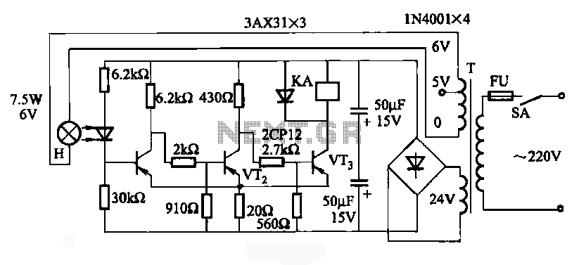
JG series of photoelectric relay circuit. To ensure reliable operation, a Schmitt trigger circuit has been incorporated. These circuits function similarly; when light strikes the photosensitive component, its internal resistance decreases, activating the transistor VT and subsequently energizing the...
The designer requires a 1-Wire host computer IO framework that operates at 1.8V. Most 1-Wire devices are unable to function at this voltage. This application recommends implementing a 1.8V 1-Wire host computer alongside a 5V 1-Wire reference design for...
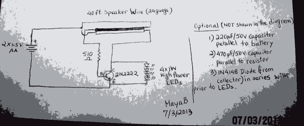
The post discusses a Joule Thief circuit that drives and illuminates four 1-watt LEDs using a single 1.5V pencil cell. The Joule Thief circuit is a minimalist boost converter designed to extract energy from low-voltage power sources, such as a...

Many published circuits that flash LEDs require 3 volts or more. This circuit utilizes a single inexpensive C-MOS IC and can flash an LED for an entire year on a single 1.5-volt AA alkaline battery cell. The circuit employs...
This 1.5 volt LED flasher runs more than a year on a single 'D' cell and alternately flashes 2 LEDs at about a 1 second rate. The circuit employs a 74HC14 CMOS hex inverter that will operate at very...
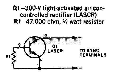
Transistor Q1 is a light-activated silicon-controlled rectifier (LASCR). The gate is activated by light entering a small lens integrated into the top cap. To operate, provide a 6-inch length of stiff wire for the anode and cathode connections, and...