
JG series circuit of a photoelectric relay

The JG series photoelectric relay circuit is designed to detect light levels and activate a relay based on the presence or absence of light. The core component of this circuit is the photosensitive element, which can be a phototransistor or a photodiode, depending on the specific application requirements. When light hits the photosensitive member, it causes a decrease in internal resistance, allowing current to flow through the circuit.
Incorporating a Schmitt trigger serves to enhance the circuit's reliability by providing hysteresis. This means that the circuit will have distinct threshold levels for turning on and off, preventing false triggering due to noise or fluctuations in light intensity. The Schmitt trigger is typically implemented using a combination of operational amplifiers or dedicated Schmitt trigger ICs.
Once the light level reaches a certain threshold, the photosensitive component activates the transistor VT. This transistor acts as a switch, allowing current to flow to the relay KA. The relay, when energized, can control larger loads or other circuits, making this configuration suitable for various automation and control applications.
The circuit's design should also consider the power supply requirements for the relay and the transistor. Proper biasing of the transistor is essential to ensure it operates within its safe limits. Additionally, protective components such as diodes may be included in the circuit to safeguard against back EMF generated by the relay coil when it is de-energized.
Overall, the JG series photoelectric relay circuit offers a robust solution for applications requiring light detection and control, leveraging the benefits of both the Schmitt trigger and relay technology.JG series of photoelectric relay circuit. For the circuit to work reliably, we have adopted the Schmitt trigger circuit. These circuits are similar, when there is light incident on the photosensitive member, the internal resistance becomes smaller, the transistor VT. Turn, relay KA box together.
Related Circuits
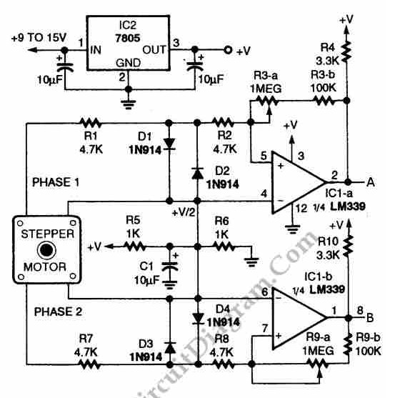
The circuit illustrated in the schematic diagram below allows for the visualization of the direction and shaft rotation of a stepper motor on an LED display. Instead of utilizing a digital rotation encoder as an input, this circuit employs...
This amplifier circuit integrates the LT1010 with a fast discrete stage and employs an LT1008-based DC stabilization loop. It features a differential stage that operates in a single-ended configuration. The described amplifier circuit is designed to enhance signal amplification while...
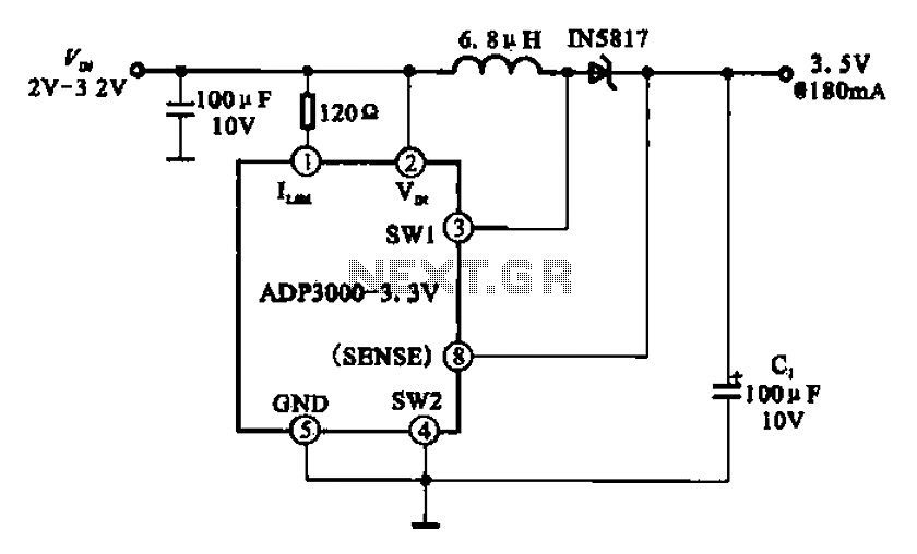
Boost 3.5V regulator circuit. This chip can boost or create a stable voltage supply from approximately 3V DC to a DC voltage of 3.5V. The boost regulator circuit is designed to increase a lower DC voltage, specifically from around 3V...
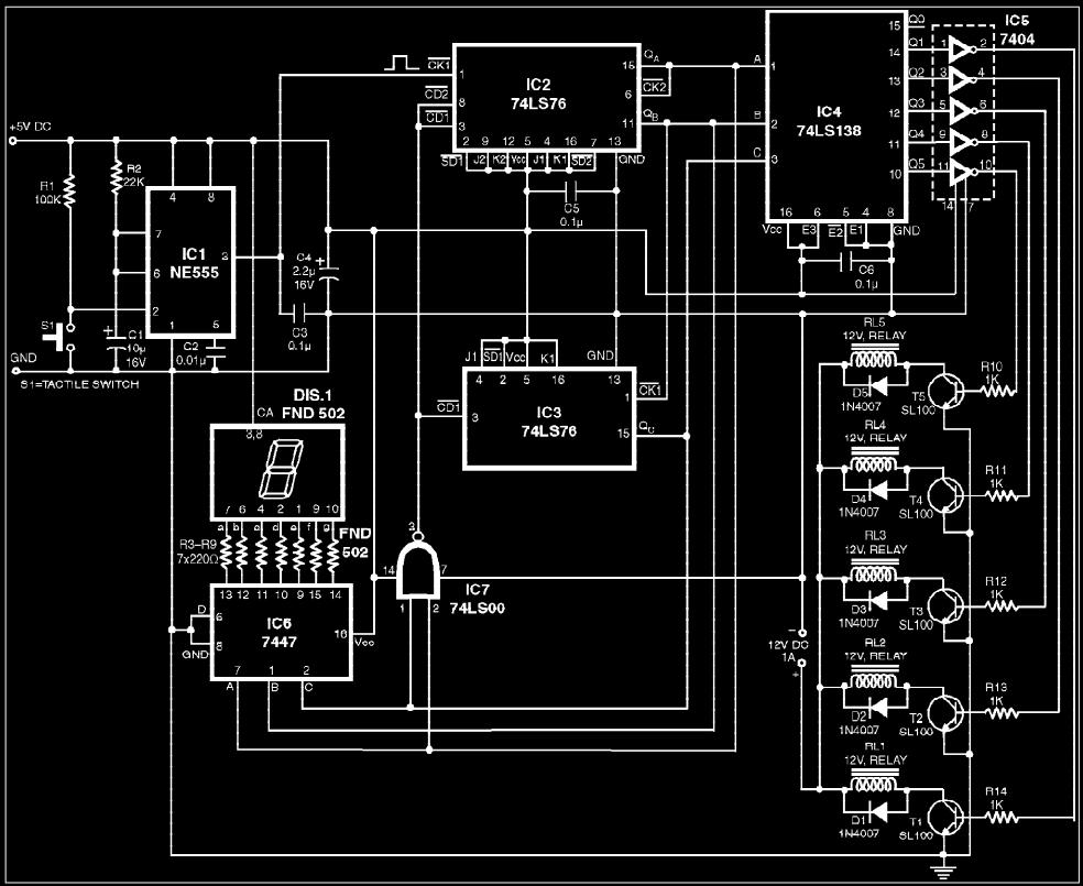
The circuit presented is a digital fan regulator that offers five speed levels, similar to conventional fan regulators. This ceiling fan controller utilizes readily available components. An optional 7-segment display with associated circuitry is included to show the selected...

The circuit utilizes a transistor (VT) and a voltage regulator (VSL) to create a constant current source, employing three regulators to enhance the performance of the regulator circuit. The described circuit employs a transistor (VT) in conjunction with a voltage...
The frequency of a crystal-controlled oscillator is maintained with high precision through the use of a quartz crystal. The frequency is primarily determined by the dimensions of the crystal, particularly its thickness, while other circuit parameters have minimal impact....