
Photo Flash Slave Unit Circuit

The circuit begins with the phototransistor Q1, which is sensitive to light pulses emitted by a photoflash unit. When a light pulse is detected, Q1 conducts, allowing the signal to be AC-coupled to the base of the amplifier Q2. This coupling is typically achieved through a capacitor that blocks any DC component of the signal while allowing the AC pulse to pass through. The amplifier Q2 amplifies the received pulse, increasing its amplitude to a level sufficient to drive the next component in the circuit.
Following amplification, the output of Q2 is connected to the gate of SCR1 (Silicon Controlled Rectifier). The SCR is a semiconductor device that acts as a switch, allowing current to flow once it has been triggered. When Q2 outputs a sufficient voltage, it triggers SCR1, enabling it to conduct and complete the circuit to the connected flash unit.
The flash unit, which is connected to terminal J1, is activated by the current flowing through SCR1. This configuration allows for a rapid response to the incoming light pulse, facilitating the triggering of the flash unit in synchronization with the original light source. The overall design is commonly used in applications where quick and reliable light detection and response are necessary, such as in automatic photography or light-activated signaling systems. Phototransistor Ql receives a light pulse from a photoflash unit. The pulse is ac-coupled to amplifier Q2. It then triggers SCR1, which triggers a flash unit that is connected to Jl.
Related Circuits

First Response Monitor, Input Selector, Game Circuit. This circuit is utilized for first response applications as it aids in monitoring various responses in games. The First Response Monitor circuit is designed to facilitate real-time monitoring and selection of input signals...
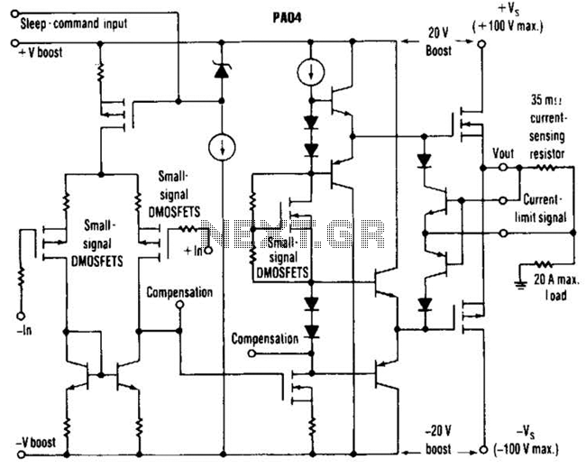
This circuit from Apex Microtechnology can deliver 180 V peak-to-peak at 90 kHz into a 4-ohm load. The PA04 can deliver 400 watts RMS into an 8-ohm load with low total harmonic distortion at frequencies exceeding 20 kHz. The circuit...
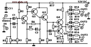
This electronic circuit is a video signal amplifier that provides a broad bandwidth amplifier with a capacity of 5 MHz. It is designed to take video signals from a VCR and amplify them adequately to drive up to three...

An audio source, such as a mixer, preamp, EQ, or recorder, is connected to the input of the Electronic Crossover Circuit. The signal can be either AC or coupled, depending on the setting of switch 51, which controls the...

The following circuit is a power amplifier circuit for an FM transmitter with an output power of 30 watts. The power amplifier circuit utilizes a power transistor of type 2SC1946A. The FM transmitter operates with a 13.8-volt DC power...
This document presents the circuit diagram of an IC-controlled emergency light with a charger, which functions as a 12V to 220V AC inverter circuit. The primary features of this circuit include automatic activation of the light during mains failure...