
Xenon Strobe Light Circuit with IC555

The circuit integrates a 555 timer configured in astable mode to create a PWM signal, which is essential for controlling the brightness of a flash in a camera application. The duty cycle of the PWM signal, which is adjustable, directly influences the amount of power delivered to the flash unit. This is achieved by varying the resistance and capacitance in the timing circuit of the 555 timer, which in turn modifies the pulse width.
The P-channel MOSFET (IRF9Z20) serves as a switch that is controlled by the output from the 555 timer. When the output on pin 3 of the 555 timer is low, the MOSFET turns on, allowing current to flow through the flash circuit. The inclusion of a 100-ohm resistor between the 555 timer and the MOSFET gate is crucial as it helps to mitigate any potential parasitic oscillations that could lead to erratic behavior of the MOSFET, ensuring stable operation.
The circuit can be further enhanced by incorporating additional components such as a microcontroller for more complex control over the PWM signal, allowing for features like adjustable flash duration and intensity based on ambient light conditions. Additionally, integrating a feedback mechanism can improve the accuracy of the flash output, ensuring consistent performance across different operating conditions. This design exemplifies the versatility and practicality of using a 555 timer in modern electronic applications, particularly in DIY projects where cost-effective solutions are sought.The circuit used to come in kit form with a surplus supplier, but it is probably more available. It shows some new concepts such as using a 555 as a pulse width modulator (PWM), and serial / parallel processors flash camera. The 555 is mounted as a pulse width modulator (from the (low) time to be determined by the regulator).
The output on pin 3 i s connected to the gate of P-channel MOSFET (IRF9Z20) through the 100R resistor to prevent parasitic oscillation of the transistor. A low signal on pin 3 causes the MOSFET to turn, so the button controls the flash output and a bit rate, by varying the duty cycle of 555 and in turn the MOSFET.
Be the first of your friends to get free diy electronics projects, circuits diagrams, hacks, mods, gadgets & gizmo automatically each time we publish. Your email address & privacy are safe with us ! 🔗 External reference
Related Circuits
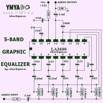
This complete high quality, low noise 5-BAND GRAPHIC EQUALIZER circuit is based around Monolithic Linear integrated circuit LA3600 manufactured by SANYO. This circuit is very easy to build and has good Quality. You can use it with Portable component...

The output frequency of this simple, low-cost active voltage-controlled oscillator circuit is based on the inherent frequency-dependent characteristics of an operational amplifier. The oscillator circuit utilizes a TL082 op-amp. Upon application of power, the circuit generates a sinusoidal wave....

The telephone line tester comprises a meter used to measure line voltage in both the on-hook and off-hook states, three resistors (including one variable resistor), a pushbutton switch, and a modular telephone connector. When the circuit is connected to...
Set R5 to read 1V RMS on an audio millivoltmeter connected to the output with R7 rotated fully clockwise, or to view a sine wave of 2.828V peak-to-peak amplitude on the oscilloscope. An audio amplifier is an electronic device...

Input voltages can range from 8 V to 30 V. The load range for the 5 V output is from 0.05 A to 5 A, while the load range for the 3.3 V output is from 0.1 A to...
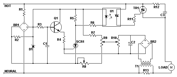
This AC motor speed controller can handle most universal type (brushed) AC motors and other loads up to about 250W. It works in much the same way as a light dimmer circuit; by chopping part of the AC waveform...