
Photo Strobe Slave Trigger Circuit

The photo strobe slave trigger circuit operates by harnessing the energy from ambient light to initiate a flash in response to a primary strobe light source. The solar cell, typically a small photovoltaic cell, converts light energy into electrical energy, producing a voltage output that is proportional to the intensity of the light it receives. When the master strobe is activated, it emits a burst of light that strikes the solar cell.
Upon receiving this light, the solar cell generates a small voltage, which is sufficient to trigger the SCR. The SCR, a semiconductor device that acts as a switch, remains off until it is triggered by a voltage applied to its gate terminal. Once the SCR is activated by the voltage from the solar cell, it allows current to flow through the strobe light circuit, causing the connected strobe to flash.
This circuit design is advantageous for photographers who require multiple flashes synchronized with a primary light source without the need for complex wiring or additional triggering mechanisms. The simplicity of the solar cell-based trigger allows for portability and ease of use in various lighting conditions. Additionally, the use of an SCR provides reliable switching capabilities, ensuring that the strobe light will flash promptly when triggered.
Overall, the photo strobe slave trigger circuit exemplifies an efficient and innovative solution for enhancing photographic lighting setups, enabling photographers to achieve creative effects with minimal equipment. The photo strobe slave trigger circuit uses a solar cell and an SCR to flash any strobe when you trigger your master strobe. The tiny solar cell produces a very small voltage when light falls on its surface.
Related Circuits

This circuit utilizes a 556 timer IC to initially generate a low-frequency square wave, which is then modulated to produce two alternating tones of approximately 400 Hz and 500 Hz. The circuit is designed to create a warble alarm...
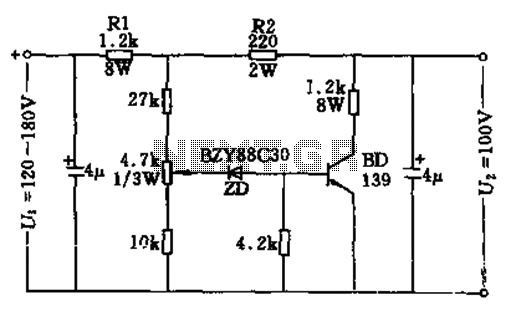
The circuit features no-load and short circuit protection mechanisms. To accommodate short circuit conditions, it is necessary to increase resistors R1 and R2 to allow for power dissipation; for example, R1 can be set to 1.2kΩ with a power...
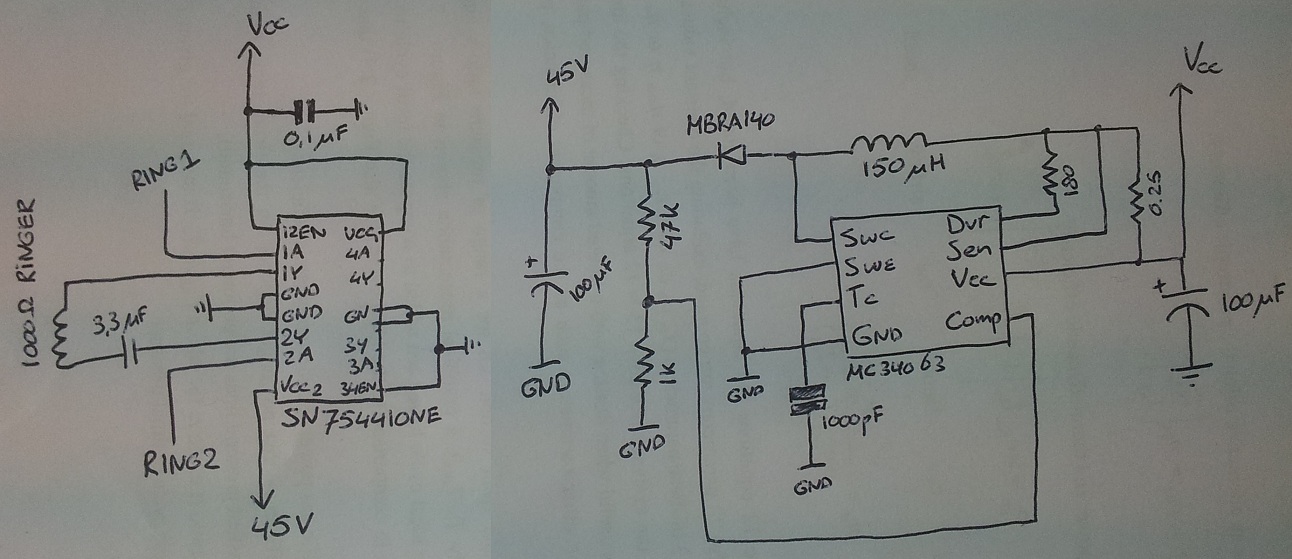
The process involves adapting an old phone for Bluetooth functionality, specifically testing the ringer circuit constructed using schematics from Sparkfun. When connecting a section of the schematic to a 3.5V source (Vcc), an output voltage of 45V is observed,...
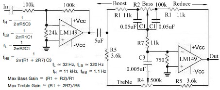
This topic continues from the more general Passive Tone Control circuit, which begins using only passive filters. This circuit follows the previous design, although the component values are different and in an alternate configuration. An audio tone control combines...
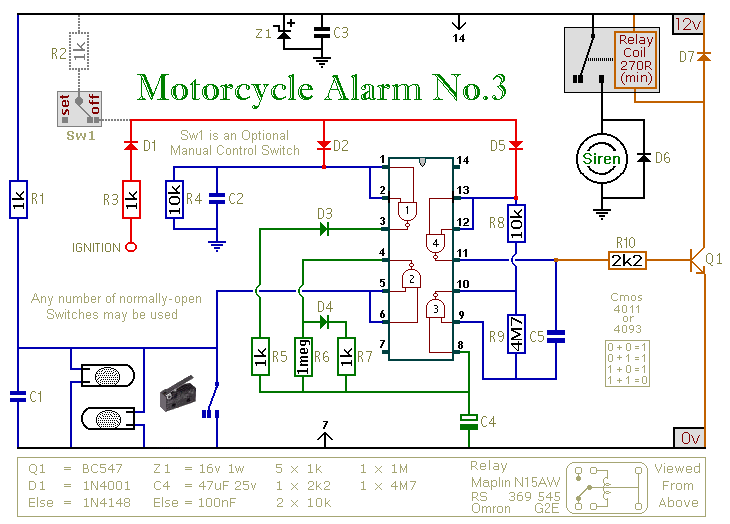
This circuit provides an intermittent siren output with an automatic reset feature. It can be operated manually through a key-switch or a hidden switch, and it can also be configured to activate automatically when the ignition is turned off....
Operating radio transmitters without a license is illegal in most countries, so caution is advised with transmitter circuits. This FM low-power circuit is designed to operate within the 87-108 MHz band II, providing a range of approximately 20 to...