
Photocell power supply (MAX630)
")
The circuit operates by converting the variable voltage from the photocells into a stable output voltage. The selection of R1 is critical, as it directly influences the output voltage based on the desired level. For the 7.2 V output, a higher resistance value (453 kΩ) is required, which limits the current flow and allows the circuit to maintain the higher voltage. Conversely, a lower resistance value (274 kΩ) is utilized for the 4.8 V output, permitting more current to flow and resulting in a lower voltage.
The efficiency of around 70% indicates that the circuit converts 70% of the input power into usable output power, with the remaining 30% lost as heat or in other forms of energy dissipation. This efficiency rating is an important parameter for applications powered by solar energy, as it directly affects the selection of solar cells. The solar cells must be capable of providing sufficient current and voltage to meet the circuit's requirements while accounting for the efficiency loss.
When designing this circuit, it is essential to consider the characteristics of the photocells, including their voltage output under varying light conditions and their ability to deliver the necessary current to sustain the desired output voltage. Proper thermal management may also be necessary to prevent overheating of components, which can affect performance and reliability. Overall, careful selection of components and design considerations will ensure optimal performance of the circuit in solar-powered applications.This circuit delivers either 4.8 or 7.2 V regulated at 15 mA with a 3-V input from a bank of photocells. R1 should be 453 k? for a 7.2-V output and 274 k? for a 4.8-Vdc output. Regulator efficiency is around 70%. This should be considered when selecting suitable solar cells.
Related Circuits

This is a single-zone alarm system featuring independently adjustable Exit, Entry, and Siren Cut-Off timers. It is compatible with standard normally-closed input devices such as magnetic-reed contacts, foil tape, and passive infrared sensors (PIRs). A mains power supply can...
The circuit is constructed using two 555 timer integrated circuits, designated as U1 and U2. U1 is configured as a variable duty cycle oscillator with a fixed time period of approximately 0.1 seconds. The duty cycle can be adjusted...
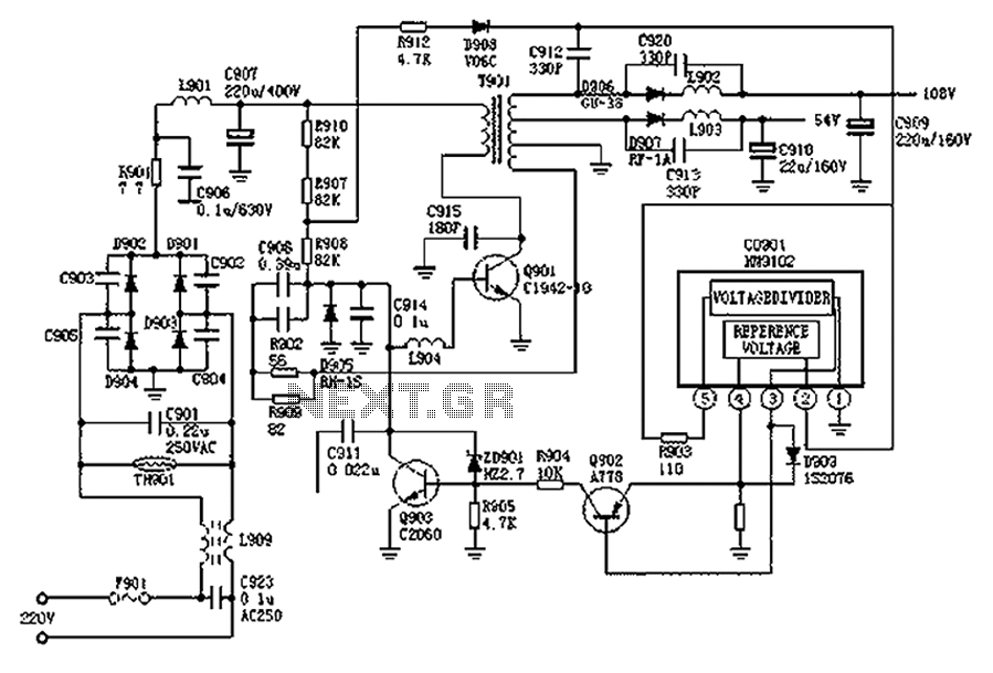
The Hitachi NP8C switching power supply circuit is illustrated in FIG. The Hitachi NP8C power models include CTP236, CEP320D, CRP350D, 450D, Furi HFC-236, 450, and Venus C37-401, C46-1, C563, among others. This circuit was widely used in early Chinese...
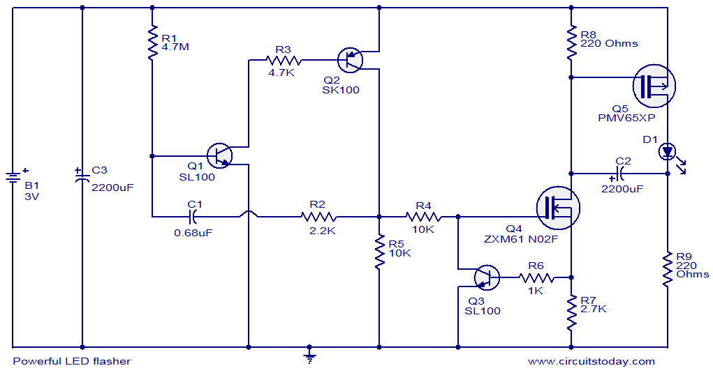
This circuit diagram illustrates a powerful LED flasher utilizing a 1W high power LED, which is widely available in the market. Transistors Q1 and Q2 are configured as an oscillator that generates positive pulses with a duration of 20...
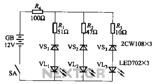
When the supply voltage falls below 10.2V, the yellow light-emitting diode (LED) VLi illuminates, indicating that the storage pool can no longer continue to discharge. Additionally, when the voltage exceeds 16.2V, the yellow, green, and red light-emitting diodes (LEDs)...
This is a variable power supply controlled by a PIC microcontroller. An LCD display is included in the circuit to show the actual output voltage and current values. A push-button switch is used to adjust the output voltage and...