
Powerful LED flasher
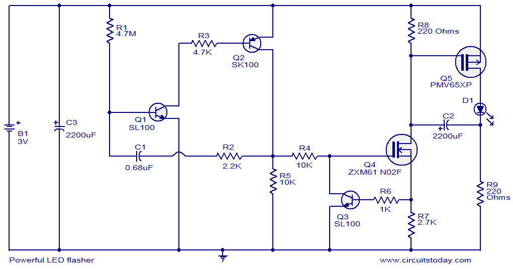
The circuit operates by leveraging the characteristics of transistors and MOSFETs to create a flashing effect for the LED. The oscillator formed by Q1 and Q2 generates a square wave signal, which oscillates between high and low states. The timing of this oscillation is controlled by the resistor-capacitor (RC) network connected to the base of Q1, determining the pulse width and frequency.
Transistor Q3 serves as a signal inverter, converting the output from the oscillator into a complementary signal that is suitable for driving the MOSFETs. MOSFET Q4 further processes this signal, ensuring that it can handle the power requirements necessary to drive the high power LED effectively.
MOSFET Q5 acts as a switch that allows current to flow through the LED D1 when it receives the appropriate signal from Q4. The LED is connected in series with a current-limiting resistor to prevent excessive current from damaging the LED. The choice of a 1W high power LED allows for bright illumination, making this circuit suitable for various applications where high visibility is required.
The overall design emphasizes efficiency and reliability, making use of solid-state components to achieve the desired flashing effect. The circuit can be powered by a suitable DC voltage source, ensuring that all components operate within their specified limits. Proper heat dissipation measures should also be considered for the MOSFETs and the LED to maintain performance and longevity.This is the circuit diagram a powerful LED flasher. High power LEDs are very common in the market now and a 1W high power LED is used here. Transistors Q1 and Q2 are wired as an oscillator which produces positive pulses of width 20ms @ ½ Hz. Transistor Q3 and MOSFET Q4 inverts this pulse and MOSFET Q5 drives the LED D1. 🔗 External reference
Related Circuits
This is a high-brightness LED driver circuit. To provide a constant-voltage output, DC/DC regulators are typically used. However, a constant-current output is the preferred method for driving LEDs. The high-brightness LED driver circuit is designed to efficiently manage the power...

This circuit employs a ring counter consisting of Q3, Q4, and Q5. Q2 functions as an oscillator that sequentially triggers the SCRs Q3, Q4, and Q5. When an SCR is activated, a 0.2 µF capacitor facilitates commutation, turning off...
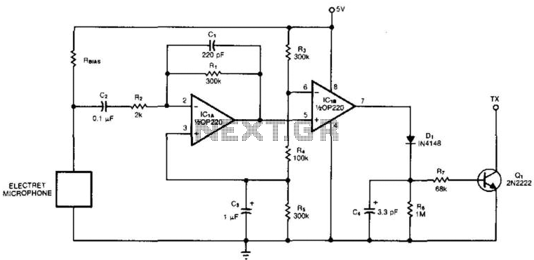
An electret microphone feeds a bandpass filter circuit (IC1A), which subsequently drives a comparator. This comparator activates Q1, a switch that conducts when audio signals from IC1B cause D1, C4, R6, and R7 to bias it ON. The circuit begins...
This circuit is used to power an LED with a voltage of 230V. The 230V must be reduced to meet the LED's voltage requirements. To achieve this, a circuit is necessary as described below. The circuit designed to power an...
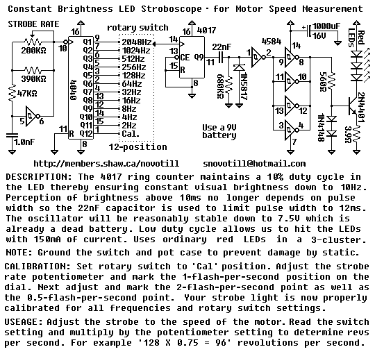
The rotary switch is available for $5.00USD as of 2003 from DigiKey under part number EG1951-ND or EG1952-ND. It is a real pain to operate this circuit without a proper switch. You can put multiple 4017 ring counters in...
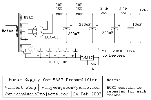
The RCA-83 rectifier utilizes 5VAC for the filament supply. The heaters for the 5687 tubes are powered by a full bridge rectifier consisting of MUR860 diodes, followed by five 10,000µF Elna capacitors. Current regulation is achieved through an LM317...
Warning: include(partials/cookie-banner.php): Failed to open stream: Permission denied in /var/www/html/nextgr/view-circuit.php on line 713
Warning: include(): Failed opening 'partials/cookie-banner.php' for inclusion (include_path='.:/usr/share/php') in /var/www/html/nextgr/view-circuit.php on line 713