
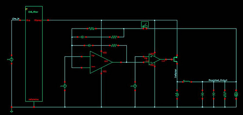
Photodiode current-to-voltage converter

The photodiode current-to-voltage converter is an essential component in optical detection systems, where precise measurement of light intensity is required. The CA3130 BiMOS op-amps are chosen for their low input bias current and high input impedance, making them ideal for detecting very low currents generated by photodiodes in response to light.
In this configuration, the photodiode is connected in reverse bias mode, which enhances its response speed and linearity. The output voltage from the op-amps is determined by the relationship between the photodiode current and the feedback resistor connected to the output. The gain of the circuit can be adjusted by changing the value of the feedback resistor, allowing for flexibility in the sensitivity of the system.
The circuit design incorporates additional features to minimize noise and improve stability. For example, bypass capacitors may be employed at the power supply pins of the op-amps to filter out high-frequency noise. Additionally, careful layout considerations are necessary to reduce parasitic capacitance and inductance that could affect the performance of the circuit.
Overall, this photodiode current-to-voltage converter circuit is vital for applications such as optical communication, spectroscopy, and light measurement in various scientific and industrial fields, where accurate and reliable detection of low light levels is crucial.The Photodiode current-to-voltage converter circuit uses three CA3130 BiMOS op amps in an application sensitive to sub-picoampere input currents. The circuit provides a ground-referenced output voltage proportional to input current flowing through the photo-diode.
🔗 External reference
Related Circuits
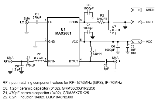
This application note presents the component values and measured performance for the MAX2681 mixer IC when tuned for GPS operation at 1575 MHz. The MAX2681 is a high-performance mixer integrated circuit designed for use in GPS applications, particularly at the...
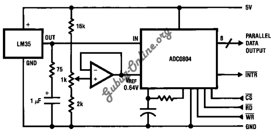
This is a design for a temperature-to-digital converter circuit that is controlled by the LM35 integrated circuit. The LM35 is a precision integrated circuit temperature sensor, whose output voltage is linearly proportional to the Celsius temperature. The circuit utilizes the...
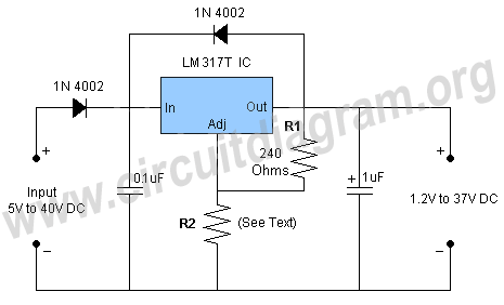
This is a simple circuit of a DC to DC converter utilizing the LM317T integrated circuit (IC). The LM317 is a well-known IC that comes in a TO-220 package. This high-performance IC features an input voltage range of 3...
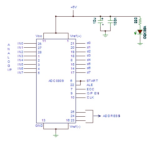
Analog to digital converter modules are utilized in microcontroller-based projects where analog signals need to be transformed into digital signals for further processing in a microcontroller. The integrated chip employed for this purpose is the ADC 0809. This post...
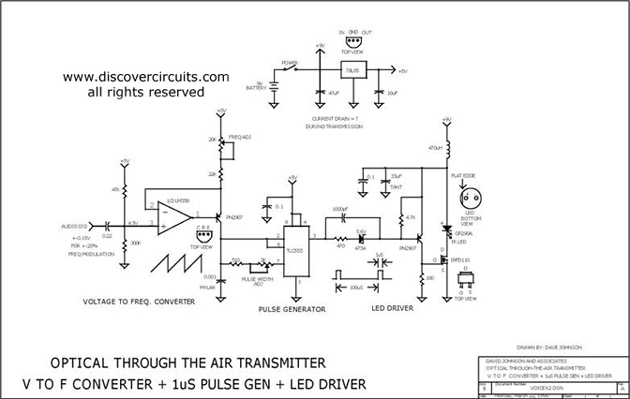
This circuit receives the signal from the amplifier and emits powerful 1μs infrared light pulses from a low-cost LED, which are frequency modulated by the audio information. The 10kHz center frequency of the pulse stream is sufficiently low, allowing...
Connect with Cadence technologists and peers in the Cadence Community. Stay informed about technology trends, news, and opinions through blogs, forums, and social networking. The Cadence Community serves as a collaborative platform for professionals in the electronics design automation (EDA)...