
UPC1651 produced by small family video transmitter circuit diagram

The working principle of this circuit involves a radio frequency signal transmitted via a 75-ohm RF cable, which is processed through components including capacitor C1, a high-pass filter formed by inductor L1, and capacitor C2. Frequencies below 45 MHz are filtered out, and the signal is then amplified by a transistor (9018) acting as a pre-amplifier, followed by further amplification using the UPC1651 integrated circuit. The output signal is transmitted through a whip antenna measuring approximately 6 inches. A voltage regulator, such as the 7805, supplies a stable 5V power to the UPC1651.
The UPC1651 is chosen for its high gain and ability to amplify high-frequency signals, while the 9018 transistor is selected for its low noise characteristics at ultra-high frequencies. The filter formed by C1, L1, and C2 has a cutoff frequency of 47 MHz. The circuit components include ceramic capacitors and carbon film resistors. Additional components provide the necessary 5V power supply and a power indicator. The inductor L1 is constructed from 3mm diameter cylindrical wire, wound tightly with 0.2mm enameled wire for 16 turns. The whip antenna is necessary for operation in the UHF band, and care must be taken in PCB design, component placement, and wiring lengths to comply with high-frequency design standards.
For assembly, the transponder circuit can be housed in a small metal enclosure, such as one from a discarded VHF tuner, after removing unnecessary mechanical and electronic components to create a shielded box. Given the simplicity of the transponder circuit, components can be soldered directly onto the circuit board, ensuring correct wiring and precise soldering. The operating current for the circuit is approximately 25 mA, with the 9018 transistor drawing around 5 mA, which can be adjusted as needed. When connecting VCRs, VCDs, and other home appliances, a 75-ohm coaxial cable should be used for the RF output, keeping the cable length as short as possible and ensuring it is fully shielded to minimize interference. With quality components, the transmitter is expected to function reliably. Circuit Overview Now many families have a TV, VCD, video recorders, game consoles, cameras and even DVD and other household appliances. If the above-mentioned appliances out of the RF signal repeater with a television signal transmitter, for a radius of about 30 meters (within the scope of the family room) TV receiver to watch, it will save a lot of inconvenience cable connections, but also more loom in different rooms watching, the TV signal repeater is like a small family television. Here is such a television signal repeaters, it has a simple circuit, low cost, easy to manufacture and so on.
t Works Circuit shown in the figure below: The working principle of this circuit is a radio frequency signal sent by the 75 ohm RF cable has a C1, a high-pass filter L1, C2 constituted, will be lower than the frequency of 45MHZ filtered, and then by the transistor in 9018, etc. after the pre-amplifier for power amplification to the upc1651 amplified by the capacitor C3, the output signal by 6 inches or so whip antenna out.
7805 or the like to provide regulated power supply 5V power supply indication for upc1615. t Selection Production upc1651 for high gain high frequency amplifier integrated circuit, 9018 is a low noise ultra high frequency transistor, C1, L1, C2 constitute a cutoff frequency of 47MHZ high-pass filter. Select frequency ceramic capacitors are capacitors with an ordinary resistance carbon film resistors.
IC2 and other components to provide 5V power supply and the power indicator .L1 production is 3mm in diameter cylinder with 0.2mm enameled wire tightly wound lap 16 bodiless. 6 inches antenna whip antenna because the unit is operating in the UHF band, in the design and production of PCB, component configuration and wiring length must comply with the requirements of high-frequency design.
t Debug molding This is the transponder circuit may be placed in a small tin to be placed in a waste of VHF tuner in. Just get rid of mechanical and electronic components which become a shielded box. Since the transponder circuit is simple, few elements can be directly soldered components on the circuit board, and make sure the wiring is correct, accurate welding!
machine operating current is about 25MA. 9018 operating current of about 5MA, it can be adjusted. VCR, VCD and other home appliances through R1 RF output cable should be selected 75 ohm coaxial cable, as short as possible, the use of fully shielded [including joints], thus reducing interference RF antenna. As long as elements of quality assurance, the transmitter can work properly.
Related Circuits
LEDs lining the headliner will fade in when the door is opened and fade out when the door is closed. The necessary components include a circuit to utilize 12V power from the vehicle to illuminate 15 LEDs and control...
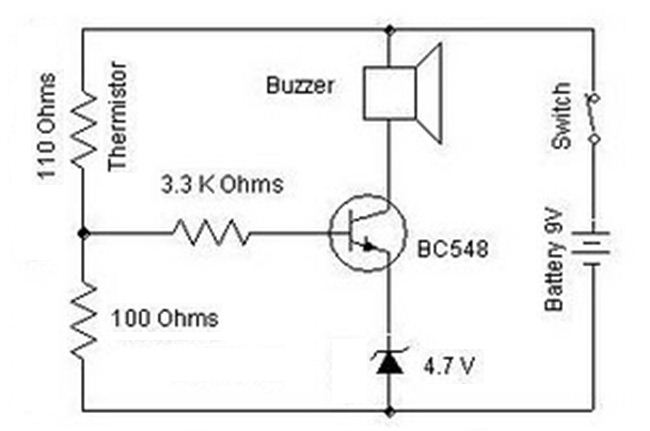
A heat sensor circuit can be utilized to control any device using a heat sensor. In this circuit, a thermistor and a resistor are connected in series, forming a potential divider circuit. The thermistor is of the Negative Temperature...
This is a simple yet effective darkness activator. It uses a light-dependent resistor (LDR) to detect light, and when no light is present, it activates an alarm from an 8-ohm speaker. The circuit can be easily modified to function...
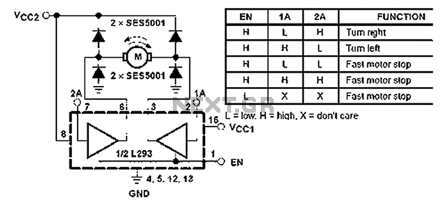
All inputs are compatible with TTL. Each output consists of a complete totem pole driver circuit, utilizing Darlington transistors and pseudo-Darlington sources. The driver enable signals, labeled as 1,2 EN and 3,4 EN, control the activation of drivers 1...
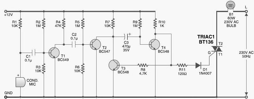
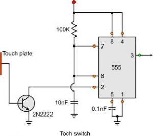
This DIY sound-activated lights circuit turns a lamp on for a brief duration when a dog barks or when a relatively loud sound is detected, creating the impression that the occupants are alerted. The condenser microphone is positioned to...

Switch-mode driven 1.5V bulbs. This device was designed on request, to control the light intensity of four filament lamps (i.e. a ring illuminator) powered by two AA or AAA batteries, for close-up pictures with a digital camera. Obviously it...