
Circuit Diagram Of Slave Flash Light Control

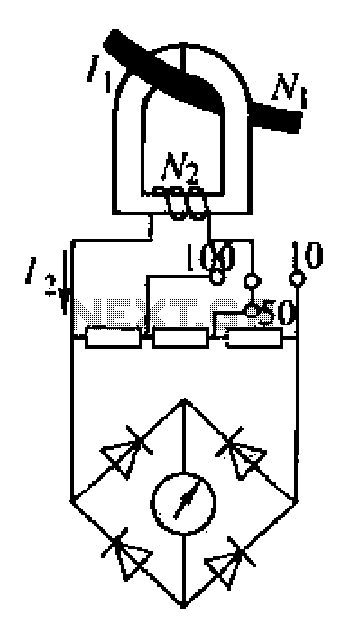
The Slave Flash Light Control Circuit is designed to enhance the functionality of flash lighting systems by enabling a secondary flash light to operate in conjunction with a primary flash. The circuit utilizes a 68 mH inductor, which plays a crucial role in the triggering mechanism. This inductor is responsible for storing energy and releasing it at the appropriate time to activate the secondary flash light.
The circuit typically comprises a power supply, a triggering mechanism, and the flash light components. The power supply provides the necessary voltage and current to the circuit, ensuring that both the primary and secondary flash lights function correctly. The triggering mechanism can be based on various sensors or timing circuits that detect the activation of the primary flash, subsequently sending a signal to the secondary flash light to illuminate.
The design may also incorporate additional components such as resistors, capacitors, and diodes to manage the flow of current, protect against voltage spikes, and filter signals. These elements work together to ensure a reliable and efficient operation of the slave flash light, providing enhanced lighting for photography or other applications where additional illumination is required.
Overall, the Slave Flash Light Control Circuit is an effective solution for achieving synchronized lighting, improving the versatility and performance of lighting setups.The following circuit shows about Slave Flash Light Control Circuit Diagram. Features: 68mH Inductor, give auto trigger for secondary flash light, .. 🔗 External reference
Related Circuits

In electronic technology, the triode utilizes a variety of general components and parts. The parameters of the triode and numerous electrical parametric measurement schemes are closely related to measurement results. Therefore, in electronic design, the base pin, typological judgment,...
An ammeter measures current in a circuit, requiring the circuit to be interrupted in series for measurement. A clamp meter, however, allows for direct measurement of current without breaking the circuit. The clamp meter's structural principle relies on a...
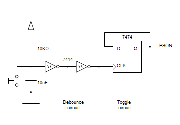
Building circuits to interface an Amiga A1200 to a PC AT/ATX power supply and tower case. To create a reliable interface between an Amiga A1200 and a PC AT/ATX power supply and tower case, it is essential to design a...
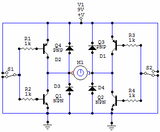
You have 4 transistors, wired as ON OFF switches. Two signal lines allow you to run the motor in one direction, when reversed, the motor runs in the other direction. It's very straightforward to use and build, but be...
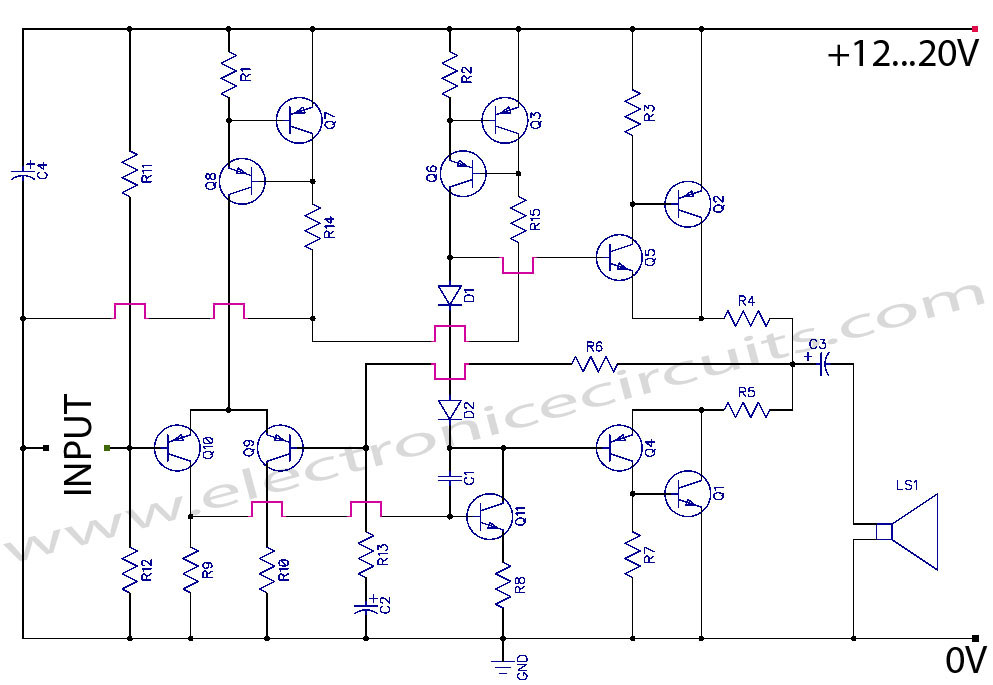
Discrete Class AB Transistor Audio Power Amplifier Circuit Diagram. This is a Class AB transistor power amplifier. It is a simple amplifier to... A Class AB transistor audio power amplifier is designed to provide high-quality amplification for audio signals while...
The tester comprises a rectifier circuit and a multivibrator circuit. The alternating current (AC) voltage is half-wave rectified by diode D1 and stored in capacitor C1. Resistor R1 is employed to limit the current through D1 to a safe...