
Phototransistor for High Impedance Voltmeter

The high impedance voltmeter circuit is particularly beneficial in applications where minimal circuit loading is essential, such as in phototransistor testing. The circuit typically consists of a high-value resistor in series with the multimeter, which allows for accurate voltage readings without significantly affecting the circuit under test. The design can include operational amplifiers configured as voltage followers to further isolate the measurement device from the circuit, ensuring that the voltmeter’s resistance does not influence the behavior of the phototransistor.
In practical implementations, the circuit may utilize a combination of resistors and capacitors to filter noise, stabilize readings, and improve response time. The choice of components should be made carefully, considering the frequency response required for the application. Additionally, the multimeter settings should be selected to match the expected voltage range, ensuring the highest possible accuracy.
When measuring the phototransistor, it is crucial to ensure that the light source is consistent, as variations in light intensity can lead to fluctuations in voltage readings. The circuit's design should accommodate variations in phototransistor characteristics, such as different types or models, which may exhibit different conductance properties under similar lighting conditions.
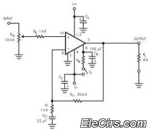
Overall, the high impedance voltmeter circuit provides a valuable tool for accurately measuring voltages in high resistance environments, particularly when working with sensitive components like phototransistors. This design allows for effective testing and validation of phototransistor functionality without compromising the integrity of the circuit being measured.This circuit is designed to provide an inexpensive way to create a High Impedance Voltmeter while making use of an inexpensive analog or digital multi meter. The circuit is specifically designed for testing phototransistors. This the figure for the circuit; When measuring voltages in high resistance circuits the resistance of the voltmeter itself
has an effect on the circuit. For example if the voltage across a 1 Mega ohm resistor is measured with a voltmeter that has an internal resistance of 1 Mega ohm then the total resistance in that part of the circuit is effectively halved (two 1 M resistors in parallel = 500K ohms). In another example; If a voltmeter with a 1 Mega ohm resistance is placed in series with a 1 Mega ohm resistance there will in effect be two - 1 Mega ohm resistances in series, the resistor in the circuit and the resistance of the voltmeter.
Under these conditions the maximum voltage that the voltmeter could show would be 1/2 of the supply voltage. This is the principle work of the circuit. Phototransistors, when used to detect a train position essentially have two states of conductance. When the phototransistor is dark it has LOW conductance and the voltage across it will be HIGH if the phototransistor is has either visible or infrared light falling on it then its conductance will be HIGH and the voltage across it will be LOW.
If the high impedance voltmeter circuit is used to measure the voltage across the phototransistor when it is dark it will not load down the circuit and should indicate almost 100 percent of the supply voltage. 🔗 External reference
Related Circuits
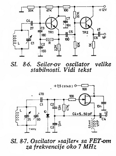
Will an LC-based oscillator be able to demonstrate performance comparable to crystals under such conditions (possibly in unusual configurations like LC-opamp) so that any energy loss at each stage is recovered, resulting in a narrower bandwidth? Examine some amateur...

This high-power audio amplifier provides top-quality performance for loudspeakers with an impedance of 4 to 8 ohms. It operates within a frequency range of 20 to 20,000 Hz and requires a voltage supply of 24 to 36 volts, with...
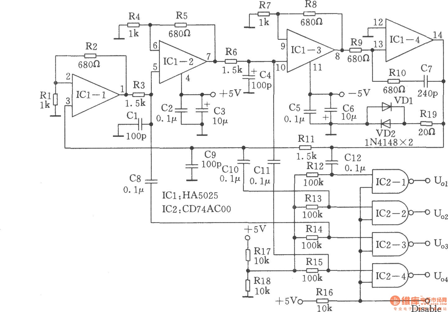
Many RC oscillators utilize an advanced circuit in the phase shift unit. This configuration employs a voltage feedback amplifier, which experiences a significant decline in gain at higher frequencies, leading to the cessation of oscillation before achieving the desired...
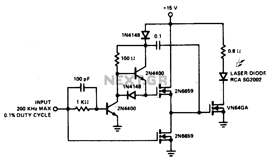
A faster driver can supply higher peak gate current to switch the VN64GA very quickly. The circuit uses a VMOS totem pole stage to drive the high power switch. The described circuit employs a high-speed driver to enhance the switching...
The LM3886 high-performance audio power amplifier circuit schematic is a crucial component in sound reproduction within audio systems. This audio power amplifier utilizes the LM3886 integrated circuit to enhance sound quality and output. The LM3886 is a high-performance audio power...

Long-distance high-voltage direct current (HVDC) lines transmit hydroelectricity from Canada's Nelson River to a converter station, where it is converted to alternating current (AC) for use in southern Manitoba's electrical grid. HVDC systems utilize direct current for bulk power...