
Photovoltaic Light Sensors In Solar Tracker

The photovoltaic light sensor circuit is designed to optimize the alignment of solar panels with respect to the sun's position, thereby enhancing energy capture efficiency. The core of the system consists of multiple photovoltaic cells that detect light intensity from different angles. These cells generate a voltage output proportional to the light they receive.
In a typical single-axis solar tracker, two or more light sensors are strategically placed on the surface of the solar panel. The output from these sensors is processed by a microcontroller or comparator circuit, which compares the voltage levels produced by each sensor. When one sensor detects more light than the other, the microcontroller sends a signal to a motor driver circuit, which adjusts the angle of the solar panel to face the light source directly.
The circuit design emphasizes cost-effectiveness by utilizing readily available components such as operational amplifiers for signal comparison and low-cost DC motors for adjustment. The simplicity of the design allows for easy implementation and maintenance, making it suitable for both residential and commercial solar applications.
To ensure accurate tracking, the circuit may include additional features such as hysteresis to prevent rapid oscillations in panel position due to fluctuating light levels. Furthermore, it may incorporate a feedback mechanism to monitor the panel's position and adjust it accordingly, ensuring optimal performance throughout the day.
Overall, this photovoltaic light sensor circuit exemplifies a practical solution for maximizing solar energy harvesting through efficient tracking mechanisms.The following circuit shows about Photovoltaic Light Sensors In Solar Tracker. Features: accurate, low cost, simple, single axis electronic solar .. 🔗 External reference
Related Circuits
This article discusses the design of an LED driver for automotive rear lights. It demonstrates that dimming is most effectively accomplished using pulse-width modulation (PWM) in conjunction with an LED driver integrated circuit (IC) that removes the requirement for...
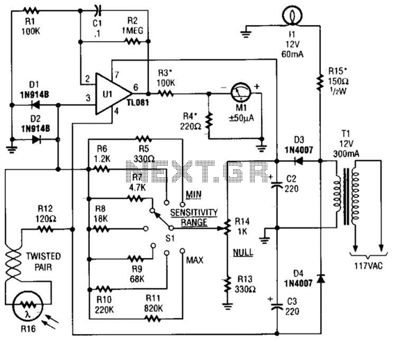
The Meter Ml is a +/-50-uA zero-center D'Arsonval meter movement driven by Ul, a TL081 FET op amp, through R3. The gain of Ul is set to 11 using resistors R1 and R2, while capacitor C1 restricts the bandwidth...
It is advisable to prototype the entire circuit using a breadboard. This method simplifies the process significantly compared to attempting to determine the connections on a small printed circuit board. Prototyping a circuit on a breadboard allows for easy modifications...
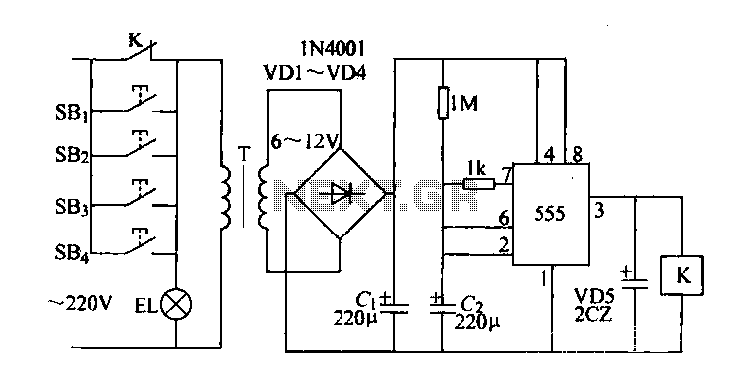
Control buttons SB1 to SB4 can be installed in various positions within a corridor. By pressing any one of these buttons, the EL horse lights will turn on. After releasing the button, the transformer and rectifier supply power to...

The way that this circuit works is as follows. The AC line voltage is rectified by D1 and D2 which connects to a voltage doubler circuit made up of the two 22uf capacitors. The Flash Freq. Pot and the...
The controller circuit illustrated in Figure 15-24 consists of a switch-type Hall integrated circuit DN838 and an astable multivibrator, which is based on the 555 timer IC. This circuit is suitable for various applications, including automatic door opening, delay...